Hardware User Guide
4-2
Xilinx Development System
This demonstration board is supported by the JTAG Programmer
Software. For more information about using this software, refer to the
JTAG Programmer Guide.
Printed Circuit Board (PCB)
The Printed Circuit Board is shipped with a 44-pin VQFP XC9536
device with two bypass capacitors, 8 LEDs with current limiting
resistors, and a header for attaching the download cable.
The PCB will accept a DPDT switch or a permanent jumper at loca-
tion SW1. The switch is used to connect or disconnect an external DC
voltage from the +5V regulator.
Prototyping Area
A prototyping area is included on the PCB. This area has 299 holes (13
columns x 23 rows) for attaching additional circuitry. The holes are
0.038 inch diameter on 0.10 inch centers. Two pairs of these holes are
connected to + 5V and GND along the left side of the prototyping
area.
Power Supply
The Demonstration Board allows the attachment of an external regu-
lated +5V power supply via the pads at J2. If a +5V regulator is
installed at location U2 with a 22uF (or larger) filter capacitor at C4,
an external DC voltage of 7V to 12V can be applied at location J3.
You can also install an outer case, battery, 5V regulator, filter capac-
itor, and on-off switch on the demonstration board. These power
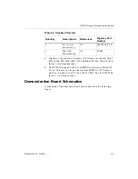
supply components can be purchased from Digi-Key, as shown in the
following table.
Table 4-1 Digi-Key Parts List
Quantity
Descriptions
References
Digi-Key Part
Number
1
DPDT Switch,
right angle.
SW1
EG1909
Содержание MultiLINX DLC4
Страница 2: ...Hardware User Guide ...
Страница 10: ...Hardware User Guide vi Xilinx Development System ...
Страница 38: ...Hardware User Guide 1 24 Xilinx Development System ...
Страница 108: ...Hardware User Guide Glossary 4 Xilinx Development System ...

