


Manual 37139C
UMT 1 - Measuring Transducer
Page 10/62
© Woodward
WARNING
All technical data and ratings indicated in this chapter are not definite! Only the values indicated under
Technical Data on page 42 are valid!
CAUTION
A circuit breaker must be located near to the unit and in a position easily accessible to the operator.
This must also bear a sign identifying it as an isolating switch for the unit.
NOTE
Inductive devices connected to the system (such as operating current coils, undervoltage tripping
units, or auxiliary/power contacts) must be connected to a suitable interference suppressor.
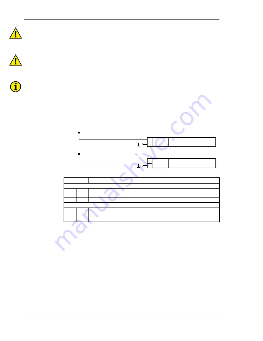
Power Supply (Standard /
Option N
)
≡≡≡≡≡≡≡≡≡≡≡≡≡≡≡≡≡≡≡≡≡≡≡≡≡
Standard
Wide-range power supply
90-265 Vac/dc
- / N
+ / L
B
A
24 Vdc
24 V DC
0 V
B
A
Power supply
Power supply
Figure 3-3: Power supply
Terminal
Description
A
max
120/400 V version
A
16 24 Vdc (18 to 30 Vdc), max. 10 W
90 to 265 Vac/dc, max. 10 W (
Option N
)
2.5 mm²
B
15 0 V reference point
2.5 mm²
690 V version
A
8
24 Vdc (18 to 30 Vdc), max. 10 W
90 to 265 Vac/dc, max. 10 W (
Option N
)
2.5 mm²
B
7
0 V reference point
2.5 mm²