background image

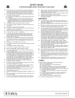
Safety

BW15_SR (15/04/2019)

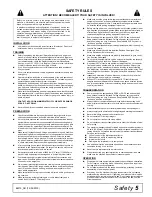
Never walk, stand, or place yourself or others under a raised wing or in 
the path of a lowering wing. Hydraulic system leak-down, hydraulic sys-
tem failures, mechanical failures, or movement of control levers can 
cause wings to drop unexpectedly and cause severe injury or death.

Full chain shielding must be installed at all times. Thrown objects could 
injure people or damage property.

If the machine is not equipped with full chain shielding, operation must 
be stopped.

This shielding is designed to reduce the risk of thrown objects. The 
mower deck and protective devices cannot prevent all objects from 
escaping the blade enclosure in every mowing condition. It is possible 
for objects to ricochet and escape, traveling as much as 300 feet 
(92m).

Never direct discharge toward people, animals, or property.

Do not operate or transport equipment while under the influence of alco-
hol or drugs.

Operate only in daylight or good artificial light.

Keep hands, feet, hair, and clothing away from equipment while engine is 
running. Stay clear of all moving parts.

Always comply with all state and local lighting and marking requirements.

Never allow riders on power unit or attachment.

Power unit must be equipped with ROPS or ROPS cab and seat belt. 
Keep seat belt securely fastened. Falling off power unit can result in 
death from being run over or crushed. Keep foldable ROPS system in 
“locked up” position at all times.

Always sit in power unit seat when operating controls or starting engine. 
Securely fasten seat belt, place transmission in neutral, engage brake, 
and ensure all other controls are disengaged before starting power unit 
engine.

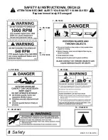
Operate tractor PTO at 1000 RPM. Do not exceed.

Look down and to the rear and make sure area is clear before operating 
in reverse.

Do not operate or transport on steep slopes.

Do not stop, start, or change directions suddenly on slopes.

Watch for hidden hazards on the terrain during operation.

Do not handle blades with bare hands. Careless or improper handling 
may result in serious injury.

Never go underneath equipment (lowered to the ground or raised) unless 
it is properly blocked and secured. Never place any part of the body 
underneath equipment or between movable parts even when the engine 
has been turned off. Hydraulic system leak down, hydraulic system fail-
ures, mechanical failures, or movement of control levers can cause 
equipment to drop or rotate unexpectedly and cause severe injury or 
death. Follow Operator's Manual instructions for working underneath and 
blocking requirements or have work done by a qualified dealer.

Keep all persons away from operator control area while performing 
adjustments, service, or maintenance.

Do not modify or alter or permit anyone else to modify or alter the equip-
ment or any of its components in any way.

 To prevent contamination during maintenance and storage, clean and 
then cover hose ends, fittings, and hydraulic ports with tape.

Do not allow bystanders in the area when operating, attaching, removing, 
assembling, or servicing equipment.

Make certain all movement of equipment components has stopped 
before approaching for service.

Raise or lower wings slowly to prevent personal injury or damage to cut-
ter.

Frequently check blades. They should be sharp, free of nicks and cracks, 
and securely fastened.

Your dealer can supply genuine replacement blades. Substitute blades 
may not meet original equipment specifications and may be dangerous.

Tighten all bolts, nuts, and screws to torque chart specifications. Check 
that all cotter pins are installed securely to ensure equipment is in a safe 
condition before putting unit into service.

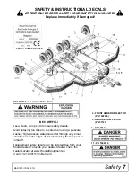
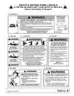
Make sure all safety decals are installed. Replace if damaged, missing, 
or illegible. (See Safety Decals section for location.)

Make sure shields and guards are properly installed and in good condi-
tion. Replace if damaged.

MAINTENANCE

Your dealer can supply original equipment hydraulic accessories and 
repair parts. Substitute parts may not meet original equipment specifica-
tions and may be dangerous.

Raise or lower wings slowly to prevent personal injury or damage to cut-
ter.

To prevent contamination during maintenance and storage, clean and 
then cover hose ends, fittings, and hydraulic ports with tape.

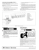
Continuous operation while the clutch is slipping could cause heat build-
up resulting in fire. Adjust slip clutch pressure by tightening springs to the 
dimension shown in the “Owner Service” section. If clutch is set to mini-
mum spring length, replace the friction disks as shown.

Never go underneath equipment (lowered to the ground or raised) unless 
it is properly blocked and secured. Never place any part of the body 
underneath equipment or between moveable parts even when the engine 
has been turned off. Hydraulic system leak down, hydraulic system fail-
ures, mechanical failures or movement of control levers can cause equip-
ment to drop or rotate unexpectedly and cause severe injury or death. 
Follow Operator’s Manual instructions for working underneath and block-
ing requirements, or have work performed by a qualified dealer.

Before dismounting power unit or performing any service or mainte-
nance, follow these steps: disengage power to equipment, lower the 3-
point hitch and all raised components to the ground, operate valve levers 
to release any hydraulic pressure, set parking brake, stop engine, 
remove key, and unfasten seat belt.

Before cleaning, servicing, adjusting, repairing or unplugging, stop tractor 
engine, place all controls in neutral, set park brake, remove ignition key, 
and wait for all moving parts to stop.

Never perform cleaning, servicing, or maintenance with engine running.

Do not disconnect hydraulic lines until machine is securely blocked or 
placed in lowest position and system pressure is released by operating 
valve levers.

Service and maintenance work not covered in OWNER SERVICE must 
be done by a qualified dealership. Special skills, tools, and safety proce-
dures may be required. Failure to follow these instructions can result in 
serious injury or death.

Explosive separation of tire and rim parts can cause serious injury or 
death. Release all air pressure before loosening bolts on wheel.

STORAGE

Before disconnecting and storing, follow these instructions:

Store on level, solid ground.

Disconnect driveline and secure up off the ground.

Lower wings to ground.

Raise cutter center section and pin transport bar in raised position.

Attach parking jack and raise tongue weight off tractor drawbar.

Place wedge blocks at front and rear of wheels on center section and 
each wing to prevent wheel rotation.

Securely block all four corners of center section and each wing with 
jackstands.

Remove hydraulic hoses after tractor is turned off and all system 
pressure is released by operating valve levers several times.

Remove safety tow chain.

Remove retainer pin and high strength drawbar pin.

Keep children and bystanders away from storage area.

SAFETY RULES

ATTENTION! BECOME ALERT! YOUR SAFETY IS INVOLVED!

Содержание BATWING BW20.50QE

Страница 1: ...OPERATOR S MANUAL BATWING ROTARY CUTTER Rev 22 10 2019 BW20 50QE BW20 60QE BW20 70QE MAN1279...

Страница 2: ...ve purchased has been carefully engineered and manufactured to provide dependable and satisfactory use Like all mechanical products it will require cleaning and upkeep Lubricate the unit as specified...

Страница 3: ...5 BLOCKING METHOD 15 LUBRICATION 16 BLADES 16 SLIP CLUTCH ADJUSTMENT 17 18 SHIELDING REPAIR 18 SERVICING TIRES SAFELY 18 CLEANING 19 TROUBLESHOOTING 20 DEALER SERVICE 21 DEALER SERVICE 21 GEARBOX MAIN...

Страница 4: ...y without notification Throughout this manual references are made to right and left directions These are determined by standing behind the equipment facing the direction of forward travel Blade rota t...

Страница 5: ...on drivelines repair and replace bearings before putting equipment into service Power unit must be equipped with ROPS or ROPS cab and seat belt Keep seat belt securely fastened Falling off power unit...

Страница 6: ...meet original equipment specifications and may be dangerous Tighten all bolts nuts and screws to torque chart specifications Check that all cotter pins are installed securely to ensure equipment is in...

Страница 7: ...clean damp cloth to clean safety decals Avoid spraying too close to decals when using a pressure washer high pressure water can enter through very small scratches or under edges of decals causing them...

Страница 8: ...MAN1279 15 04 2019 7 PN 15503 9 PN 18865 11 PN W19924 8 PN 18864 6 PN 18866 5 PN 15922 OR 18 PN 608235 SAFETY INSTRUCTIONAL DECALS ATTENTION BECOME ALERT YOUR SAFETY IS INVOLVED Replace Immediately If...

Страница 9: ...y 9 MAN1279 15 04 2019 SAFETY INSTRUCTIONAL DECALS ATTENTION BECOME ALERT YOUR SAFETY IS INVOLVED Replace Immediately If Damaged 12 PN 1045604 13 PN 1003751 15 PN 18964 16 PN 15502 14 PN 18877 10 PN 3...

Страница 10: ...10 Declaration of Conformity MAN1279 15 04 2019...

Страница 11: ...cm 20 in This will minimize joint knock and damage to drive components Figure 1 Cutter to Tractor Connection Mechanical Connection 1 Remove unauthorized tow device by unlocking and removing specific d...

Страница 12: ...om mended PTO operating RPM Be sure operator is familiar with all controls and can stop tractor and cutter quickly in an emergency The operator should give complete undivided atten tion to operating t...

Страница 13: ...r untrained persons to operate equipment Do not allow bystanders in the area when operating attaching removing assembling or servicing equipment Make sure spring activated locking pin or collar slides...

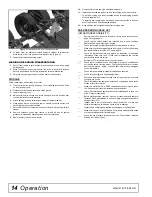
Страница 14: ...RESPONSIBILITY ___ Review and follow all safety rules and safety decal instructions on page 7 through page 9 ___ Check that all safety decals are installed and in good condition Replace if damaged mi...

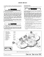
Страница 15: ...d disconnect driveline from tractor PTO Never go underneath equipment lowered to the ground or raised unless it is properly blocked and secured Never place any part of the body underneath equipment or...

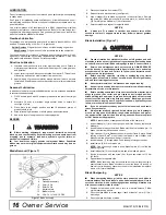
Страница 16: ...sure to install blade cutting edge to lead in correct rotation Service and maintenance work not covered in OWNER SERVICE must be done by a qualified dealership Special skills tools and safety procedur...

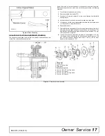
Страница 17: ...slip freely disassemble and clean the thrust plate faces 4 flange yoke 1 and clutch hub 3 6 Reassemble clutch 7 Tighten Belleville spring plate 5 until it is against the thrust plate 4 of the clutch a...

Страница 18: ...lip Clutch Assembly SHIELDING REPAIR Full chain shielding must be installed at all times Thrown objects could injure people or damage property If the machine is not equipped with full chain shielding...

Страница 19: ...dically or Before Extended Storage Clean large debris such as clumps of dirt grass crop residue etc from machine Remove the remainder using a low pressure water spray 1 Be careful when spraying near s...

Страница 20: ...et height so blades do not frequently hit ground Excessive lush and tall vegetation Recut at 90 to first pass Excessive side skid wear Running with skids continuously on ground Raise cutting height or...

Страница 21: ...seal squarely on housing spring loaded lip toward housing Select a piece of pipe or tubing with an OD that will sit on the outside edge of the seal but will clear the housing Tubing with an OD that i...

Страница 22: ...the correct diameter and a hand press Secure with shim 13 and snap ring 10 10 Secure snap ring 11 on input shaft 3 if not already secure 11 Place gear 1 through top of housing and align gear 1 and ge...

Страница 23: ...b cap 11 and press bearing cone 7 on to output shaft 13 8 Slide gear 19 over output shaft 13 and secure with nut 20 and cotter pin 21 9 Check end play of shaft by moving it in and out If end play is m...

Страница 24: ...and thread puller screw 6 into nut from bottom Tighten until pad is solid against gearbox shaft For best results strike head of puller screw with a hammer while tightening with a wrench 7 For removal...

Страница 25: ...m 800 lbs ft 3 Install cotter pin 70 through slot in nut and bend ends over Figure 17 Crossbar Assembly Installation UNIVERSAL JOINT REPAIR Figure 18 U Joint Exploded View U Joint Disassembly 1 Remove...

Страница 26: ...ps by placing a drift or socket slightly smaller than the cup on cup and rap with a hammer Install snap ring and repeat on opposite cup 4 Repeat Step 1 and Step 2 to install remaining cups in remainin...

Страница 27: ...is securely blocked or placed in lowest position and system pressure is released by operat ing valve levers Always wear relatively tight and belted clothing to avoid entangle ment in moving parts Wea...

Страница 28: ...des 4 Crossbar Installation Center Section 1 Repeat steps for center crossbar and blade installation 2 Use crossbar 1 and offset CCW blades 3 and flat blades 4 Install Stationary Blades Center Section...

Страница 29: ...parallel to the rotating blades point toward the center of the gearbox and rear of cutter and overlap rotating blades approximately 101 6 mm 4 inches 4 Repeat steps to install stationary mounting bra...

Страница 30: ...ow customer how to determine the turning limits of the CV PTO driveline ___ Show customer the safe proper procedures to be used when mount ing dismounting and storing equipment ___ Make customer aware...

Страница 31: ...OR ALL MODELS BW20 50QE CENTER FRAME ASSEMBLY 66 67 WING ASSEMBLY 68 TONGUE ASSEMBLY 69 WING CENTER GEARBOX ASSEMBLY 70 71 CENTER DRIVE DECK ASSEMBLY 72 WING DRIVE ASSEMBLY 73 CROSSBAR ASSEMBLY 74 SHR...

Страница 32: ...des 11975 W11893 see page 41 8 11817 1 Hose 25 ID x 25 NPT x 230 9 11975 1 1 2 NPT Vent Plug 10 13316 4 Compression Spring 3 00 50 6 2 11 24098A 1 1 1 4 Cylinder Stroke Control Set 12 25475 4 HHCS 1 2...

Страница 33: ...r Spring Arm Ctr 13 611403RP 1 WA Wheel Yoke Arm Spring 14 1017149 1 Bar DR 1 25 x 8 85 15 1044932 1 Pin 1 00 x 11 50 16 1045655 1 Nut HFN 5 16 NC Dri Loc Patch 17 1046049 2 Pin Spirol 3 8 x 3 Hvy ITE...

Страница 34: ...1 SPR CMP 3 25 69 9 52200 15 611403RP 1 WA Wheel Yoke Arm Spring 16 611412RP 1 WA Lower Spring Arm Ctr 17 1017149 1 Bar DR 1 25 x 8 85 18 1044932 1 Pin 1 00 x 11 50 19 1045655 1 Nut HFN 5 16 NC Dri Lo...

Страница 35: ...assembly cup and cone 8 1019592 A S Gasket 15 mm 9 1019593 A S Gasket 25 mm 10 1019594 A S Gasket 45 mm 11 1019612 2 Hub cap 12 1019590 2 Oil seal 13 1019576 2 Output shaft 14 1019603 1 Spacer 15 101...

Страница 36: ...1 Yoke Inboard 13 40764 1 Spring Pin 10 x 90 14 603768 1 Inner Profile 15 603769 1 Profile w Grease fitting 16 598672 1 Grease fitting 17 40751 1 Yoke Inboard 18 40765 1 Spring Pin 19 1045583 1 Cross...

Страница 37: ...602850 6 Screw Slotted Cheese M5 x 0 8 x 16 8 602851 6 Nut Hex Nylock M5 x 0 8 x 16 9 603912 1 Light CE RT Triangle 10 603913 1 Light CE LT Triangle 11 603968RP 2 Link CE Front Upright 12 609550RP 2...

Страница 38: ...x 1 Carriage bolt GR5 17 14350 3 8 NC Flanged lock nut 18 1027189 1 Rear chain plate center short 19 1007852 1 Pin 7 to 9 chains REF PART QTY DESCRIPTION 1 1029881 1 Front center chain plate 2 102988...

Страница 39: ...2 Carriage bolt GR5 15 11900 1 2 NC Flanged lock nut 16 6697 3 8 NC x 1 Carriage bolt GR5 17 14350 3 8 NC Flanged lock nut REF PART QTY DESCRIPTION 1 1029885 1 Front wing chain plate inner 2 1029884 1...

Страница 40: ...eavy wheel hub with cups includes items 6 7 14 3 1017033 1 Axle 4 1017027 1 Seal 5 1017028 1 Bearing cone 6 1017036 1 Bearing cup 7 1017037 1 Bearing cup 8 1017029 1 Bearing cone 9 1017031 1 Washer 10...

Страница 41: ...on seal 2G 1 Piston O ring 3 N S N S 1 Cylinder housing rod end 4 N S N S 1 Piston 5 N S N S 1 Jam nut 6 N S N S 4 Cylinder tie rod 7 3 1 2 Pipe plug 8 N S N S 1 Cylinder housing butt end 9 N S N S 2...

Страница 42: ...includes items 2A 2F 2A 2 Cap O Ring 2B 1 Piston Seal 2C 1 Rod O Ring 2D 1 Cap Seal 2E 1 Wiper Seal 2F 2 Backup Seal 3 N S 1 Cylinder Housing Rod End 4 N S 1 Piston 5 N S 1 Jam Nut 6 N S 4 Cylinder T...

Страница 43: ...gment 3 1 1 1 4 Segment 4 1 1 Segment 5 1 3 4 Segment REF PART QTY DESCRIPTION A 8811 1 Crossbar puller complete 1 19914 2 Crossbar puller clevis 2 3097 4 5 8 NC x 4 1 2 HHCS GR5 3 230 4 5 8 NC Hex nu...

Страница 44: ...l 3 12 x 3 25 x 10 00 12 12612 1 Gear winch 5 1 to 1 13 12642 1 Winch cable clamp kit 14 11790 1 C Hook 1 4 cable 15 52479 1 Cable 1 4 x 24 ft 16 11789 2 Clip 1 4 cable 17 839 HHCS 3 8 NC x 1 GR5 18 5...

Страница 45: ...Common Components 45 MAN1279 15 04 2019 NOTES...

Страница 46: ...46 50 Series Parts MAN1279 15 04 2019 CENTER FRAME ASSEMBLY BW20 50QE...

Страница 47: ...004251 1 SMV Bracket 25 1017055 5 Flag Pin 1 25 x 6 5 26 1017143RP 1 Lug Bent 25 x 2 25 x 11 0 27 1019600 1 Plug Breather M18 x 1 5 28 1027035RP 2 WA Skid BW240 29 1027110RP 1 WA Splitter Shield BW240...

Страница 48: ...Wing 7 1027099RP 1 BW240 Skid LT Left Wing 8 1027120RP 1 WA Wing Gearbox Shield BW240 9 1027246RP 1 Angle RT Wing Right Wing 10 1027247RP 1 Angle LT Wing Left Wing 11 1041071 4 Screw HFS M8 1 25 x 16...

Страница 49: ...1 00 x 2 26 9 52232 1 Swivel Parking Jack 10 603774 1 Coupler Ball K80 11 603802 1 Coupler Towing Eye 40 mm 12 603805 1 WA BW20E Hitch Europe 13 603806 1 WA BW20E Ball Hitch Europe 14 611470 1 WA BW20...

Страница 50: ...50 50 Series Parts MAN1279 15 04 2019 WING CENTER GEARBOX ASSEMBLY BW20 50QE...

Страница 51: ...2 57471 57471 57471 Shim 70 3 x 84 7 14 1 57329 57329 57329 Castle nut M40 x 1 5P 15 1 39323 39323 39323 Castle nut M30 x 2 0P 16 1 57471 57471 57471 Shim 50 3 x 70 3 17 1 57471 57471 57471 Shim 40 3...

Страница 52: ...5 57416 1 Friction clutch 1340 1 3 4 20 spline 6 57438 1 Flange yoke 7 57432 2 Friction disc 8 57440 1 Hub 1 3 4 20 spline REF PART QTY DESCRIPTION 9 57434 1 Thrust plate 10 57439 1 Belleville spring...

Страница 53: ...9 1 Support bearing 12 1045593 1 Inner shield 13 1045595 1 Profile and sleeve 14 33347 1 Decal Danger Guard Missing REF PART QTY DESCRIPTION 15 40779 1 Grease fitting 16 44677 1 Inboard yoke S5 17 101...

Страница 54: ...ZP 2 8820KT 1 Kit Blade 8820 STD 3 8825KT 1 Kit Blade 8825 STD 4 10520RP 2 18 GA 1 1 2 Blade Pin Shim 5 13946RP 2 20 GA 1 1 2 Blade Pin Shim 6 32603RP 2 Keyhole Plate Special 7 32604RP 2 Blade Pin Lo...

Страница 55: ...50 Series Parts 55 MAN1279 15 04 2019 NOTES...

Страница 56: ...56 60 Series Parts MAN1279 15 04 2019 CENTER FRAME ASSEMBLY BW20 60QE...

Страница 57: ...urope 24 1004251 1 SMV Bracket 25 1017055 5 Flag Pin 1 25 x 6 5 26 1017143RP 1 Lug Bent 25 x 2 25 x 11 0 27 1019600 1 Plug Breather M18 x 1 5 28 1027035RP 2 WA Skid BW240 29 1027110RP 1 WA Splitter Sh...

Страница 58: ...RT Right Wing 8 1027099RP 1 BW240 Skid LT Left Wing 9 1027120RP 1 WA Wing Gearbox Shield BW240 10 1027246RP 1 Angle RT Wing Right Wing 11 1027247RP 1 Angle LT Wing Left Wing 12 1041071 4 Screw HFS M8...

Страница 59: ...x 1 00 13 301014 1 Bolt Mach 3 4 NC x 9 14 603774 1 Coupler Ball K80 15 603802 1 Coupler Towing Eye 40 mm 16 603805 1 WA BW20E Hitch Europe 17 603806 1 WA BW20E Ball Hitch Europe 18 611434RP 1 WA Tong...

Страница 60: ...60 60 Series Parts MAN1279 15 04 2019 WING CENTER GEARBOX ASSEMBLY BW20 60QE...

Страница 61: ...Snap ring 85 UNI7437 11 1 57321 57321 57321 Snap ring 50 UNI7435 12 1 57456 57456 57456 Shim 45 3 x 2 5 13 2 57471 57471 57471 Shim 70 3 x 84 7 14 1 57329 57329 57329 Castle nut M40 x 1 5P 15 1 57308...

Страница 62: ...5 57416 1 Friction clutch 1340 1 3 4 20 spline 6 57438 1 Flange yoke 7 57432 2 Friction disc 8 57440 1 Hub 1 3 4 20 spline REF PART QTY DESCRIPTION 9 57434 1 Thrust plate 10 57439 1 Belleville spring...

Страница 63: ...9 1 Support bearing 12 1045593 1 Inner shield 13 1045595 1 Profile and sleeve 14 33347 1 Decal Danger Guard Missing R E F PART QTY DESCRIPTION 15 40779 1 Grease fitting 16 44677 1 Inboard yoke S5 17 1...

Страница 64: ...Kit Blade 8820 STD 3 8825KT 1 Kit Blade 8825 STD 4 10520RP 2 18 GA 1 1 2 Blade Pin Shim 5 13946RP 2 20 GA 1 1 2 Blade Pin Shim 6 32603RP 2 Keyhole Plate Special 7 32604RP 2 Blade Pin Lock Clip Spec 8...

Страница 65: ...T 6 Blade 5 x 4 x 22 5 flat 5 39089 3 Blade 38 x 4 x 11 13 double edge 6 1014164 2 Mounting bracket bent 7 39069 6 Blade pin R E F PART QTY DESCRIPTION 8 39127 6 Bushing 9 39128 6 Jam nut 1 1 4 10 454...

Страница 66: ...66 70 Series Parts MAN1279 15 04 2019 CENTER FRAME ASSEMBLY BW20 70QE...

Страница 67: ...5 Flag Pin 1 25 x 6 5 25 1017143RP 1 Lug Bent 25 x 2 25 x 11 0 26 1019600 1 Plug Breather M18 x 1 5 27 1019607 1 Asy Breather Dip Stick 28 1027035RP 2 WA Skid BW240 29 1027110RP 1 WA Splitter Shield B...

Страница 68: ...Skid RT Right Wing 8 1027099RP 1 BW240 Skid LR Left Wing 9 1027120RP 1 WA Wing Gearbox Shield BW240 10 1027246RP 1 Angle RT Wing Right Wing 11 1027247RP 1 Angle LT Wing Left Wing 12 1027298 1 Drv Asy...

Страница 69: ...x 1 00 13 301014 1 Bolt Mach 3 4 NC x 9 14 603774 1 Coupler Ball K80 15 603802 1 Coupler Towing Eye 40 mm 16 603805 1 WA BW20E Hitch Europe 17 603806 1 WA BW20E Ball Hitch Europe 18 611434RP 1 WA Tong...

Страница 70: ...70 70 Series Parts MAN1279 15 04 2019 WING CENTER GEARBOX ASSEMBLY BW20 70QE...

Страница 71: ...1 1019591 1019591 Output oil seal 16 1 1019578 1019578 1019578 Output shaft 17 1 1011758 1019586 1011758 Output gear 18 1 1019605 1019605 1019605 Bearing adjustment nut 19 1 1 8 x 2 1 2 Cotter pin 20...

Страница 72: ...2400 1 3 4 20 spline 6 1016489 1 Flange yoke 7 57432 4 Friction disc 8 1016490 1 Hub 1 3 4 20 spline clutch 9 1016498 1 Lock assembly 10 57443 1 Drive plate REF PART QTY DESCRIPTION 11 1016491 1 Clut...

Страница 73: ...Outer profile sleeve includes items 14 15 14 33347 1 Decal danger guard missing 15 40779 1 Grease fitting 16 40751 1 Inboard yoke REF PART QTY DESCRIPTION 17 1019109 1 Friction clutch 2500 1 3 4 20 sp...

Страница 74: ...R5 ZP 2 8820KT 1 Kit Blade 8820 STD 3 8825KT 1 Kit Blade 8825 STD 4 10520RP 2 18GA 1 1 2 Blade Pin Shim 5 13946RP 2 20GA 1 1 2 Blade Pin Shim 6 32603RP 2 Keyhole Plate Special 7 32604RP 2 Blade Pin Lo...

Страница 75: ...T 6 Blade 5 x 4 x 22 5 flat 5 39089 3 Blade 38 x 4 x 11 13 double edge 6 1014164 2 Mounting bracket bent 7 39069 6 Blade pin REF PART QTY DESCRIPTION 8 39127 6 Bushing 9 39128 6 Jam nut 1 1 4 10 4548...

Страница 76: ...1 2 467 634 722 979 1020 1383 Diameter Thread Pitch Millimeters Wrench Size COARSE THREAD FINE THREAD Diameter Thread Pitch Millimeters MARKING ON HEAD MARKING ON HEAD Metric 8 8 Metric 10 9 Metric 8...

Страница 77: ...HHCS Hex Head Cap Screw HT Heat Treated JIC Joint Industry Council 37 Degree Flare LH Left Hand LT Left m Meter mm Millimeter M Male MPa Mega Pascal N Newton NC National Coarse NF National Fine NPSM...

Страница 78: ...4 Table of Contents 3 Warranty Product 79 Replacement Parts 80 OPERATION Connecting Cutter to Tractor 12 Cutting Height Adjustment 11 CV Driveline Turning Limits 11 Hydraulic Connection 11 Interferenc...

Страница 79: ...proof of purchase within thirty 30 days after such defect or noncompliance is discovered or should have been discovered routed through the dealer and distributor from whom the purchase was made transp...

Страница 80: ...fective or in noncompliance with this Warranty The product must be returned to WOODS with proof of purchase within thirty 30 days after such defect or noncompliance is discovered or should have been d...

Страница 81: ...MANUEL DE L UTILISATEUR BATWING FAUCHEUSE ROTATIVE R v 15 04 2019 BW20 50QE BW20 60QE BW20 70QE MAN1279...

Страница 82: ...rer un usage fiable et satisfaisant Comme tous les produits m caniques il doit tre nettoy et entretenu Graissez l unit comme indiqu Respectez les informations de s curit du pr sent manuel et les consi...

Страница 83: ...TION 14 ENTRETIEN EFFECTU PAR LE PROPRI TAIRE 15 ENTRETIEN EFFECTU PAR LE PROPRI TAIRE 15 M THODE D IMMOBILISATION 15 LUBRIFICATION 16 LAMES 16 R GLAGE DE L EMBRAYAGE A FRICTION 17 18 R PARATION DE LA...

Страница 84: ...ines sans fournir de pr avis Ce manuel contient certaines informations faisant une diff rence entre le c t droit et le c t gauche Le c t est d ter min en se tenant derri re l quipement et en faisant f...

Страница 85: ...es protections d arbre de transmission avant de mettre l quipement en service Avant de mettre l unit motrice en marche s assurer du bon tat des protec tions sur tous les arbres de transmission de l qu...

Страница 86: ...issures et correctement fix es Le concessionnaire peut fournir les lames de rechange qui conviennent Les autres lames risquent de ne pas satisfaire les crit res de l quipement d origine et m me de pos...

Страница 87: ...ession peut p n trer par de tr s petites gratignures ou sous les bords des autocollants et les d coller ou s parer Il est possible de commander gratuitement des autocollants de s curit de rechange aup...

Страница 88: ...R f 15503EF 9 R f 18865EF 11 R f W19924EF 8 R f 18864EF 6 R f 18866EF 5 R f 15922EF OU 18 R f 608235 AUTOCOLLANTS S CURIT ET INFORMATIONS ATTENTION FAIRE PREUVE DE VIGILANCE LA S CURIT EN D PEND rempl...

Страница 89: ...19 AUTOCOLLANTS S CURIT ET INFORMATIONS ATTENTION FAIRE PREUVE DE VIGILANCE LA S CURIT EN D PEND remplacer imm diatement si endommag 12 R f 1045604EF 13 R f 1003751EF 15 R f 18964EF 16 R f 15502EF 14...

Страница 90: ...10 Declaration of Conformity MAN1279 15 04 2019 10 D claration de conformit MAN1279 15 04 2019...

Страница 91: ...e la faucheuse au tracteur Assemblage m canique 1 Retirer le dispositif de remorquage non autoris en d verrouillant et en retirant le dispositif sp cifique 2 Monter la faucheuse l aide d un illet de r...

Страница 92: ...cheuse Augmenter les gaz pour atteindre la vitesse de fonctionnement recommand e de la PDF S assurer que l op rateur conna t bien toutes les commandes et est capable d arr ter rapidement le tracteur e...

Страница 93: ...ruction arr ter imm diatement l unit motrice et l quipement Couper le moteur retirer la cl et r parer les d g ts ventuels avant de reprendre le travail Ne jamais laisser un enfant ou une personne non...

Страница 94: ...onne surtout pas les enfants s approcher de la remise LISTE DECONTR LE AVANT L UTILISATION RESPONSABILIT DU PROPRI TAIRE ___ Passer en revue et suivre toutes les r gles de s curit et instructions des...

Страница 95: ...eur retirer la cl et d crocher l arbre de transmission au niveau de la PDF du tracteur Ne jamais se placer sous un quipement qu il soit abaiss au sol ou relev tant qu il n est pas correctement immobil...

Страница 96: ...dans le sens inverse sur les bo tes d engrenages droite et centrale vues d en haut de la faucheuse Veiller installer la lame de raclage de fa on attaquer la premi re en une rotation correcte Les trava...

Страница 97: ...rt Belleville 5 4 Immobiliser le moyeu d embrayage 3 et tourner l arbre pour s assurer que l embrayage glisse 5 Si l embrayage ne glisse pas librement d sassembler et nettoyer les m plats de la plaque...

Страница 98: ...A PROTECTION Une protection compl te de la cha ne doit toujours tre install e Les objets projet s peuvent blesser des personnes ou endommager des biens Si la machine n est pas quip e d une protection...

Страница 99: ...ou avant un remisage prolong liminer les gros d bris comme les amas de terre d herbe de r sidus de r colte etc de la machine Enlever les autres d bris l aide d une eau pulv ris e basse pression 1 Fai...

Страница 100: ...ouvent le sol V g tation trop fournie et trop haute Recouper 90 par rapport la premi re passe Usure excessive sur le patin lat ral Utilisation avec les patins constamment au sol Augmenter la hauteur d...

Страница 101: ...8 po 1 5 16 po 306 416 474 642 669 907 1 po 1 1 2 po 467 634 722 979 1 020 1 383 Diam tre et pas du filetage millim tres Taille de la cl FILET NORMAL FILET FIN Diam tre et pas du filetage millim tres...

Страница 102: ...hexagonal HT Trait thermiquement JIC Joint Industry Council vasement de 37 LH C t gauche LT Gauche m M tre mm Millim tre M M le MPa M gapascal N Newton NC Filet am ricain gros NF Filet am ricain fin N...

Страница 103: ...de s curit 17 18 Hauteur de coupe 12 S S CURIT Autocollants S curit et Informations 7 8 9 Explications des symboles de s curit 2 Listes de contr le Liste de contr le avant l utilisation responsabilit...

Страница 104: ...produit doit tre retourn chez WOODS avec la preuve d achat dans les trente 30 jours apr s que le d faut ou la non conformit a t d couvert ou aurait d tre d couvert en passant par le revendeur et le d...

Страница 105: ...tion le consid re comme d fectueux ou non conforme cette garantie Le produit doit tre retourn chez WOODS avec la preuve d achat dans les trente 30 jours apr s que le d faut ou la non conformit a t d...

Отзывы: