ProVU4 Controller, Profiler & Recorder/Controller - Product Manual
59407, Issue 3 – May 2011
PC Software
Page 171
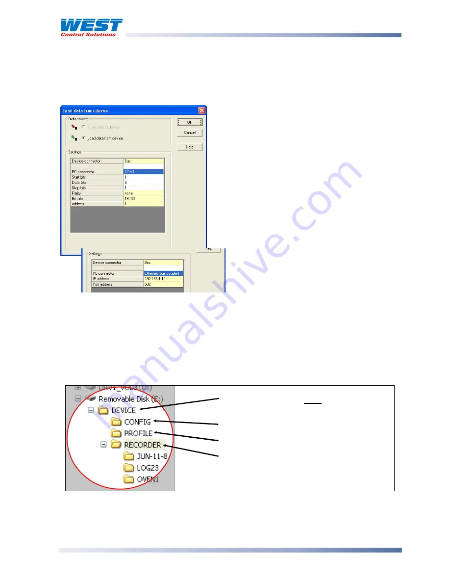
A communications settings screen is shown whenever the user attempts to connect to the
instrument from the software. The settings must be correct in order for communications to
work successfully. First correctly select Configuration Socket or Bus as the Device connector,
and select the PC Serial Com port that you have connected to
For Modbus TCP, select Ethernet (bus coupler).
If connecting via the configuration port, the Start
and Stop bits must be 1 and Data bits 8. Parity
must be None and address 1. The data bit-rate
should be 4800 if Slot A is fitted with an Auxiliary
input, 9600 if the Ethernet option is installed or
19,200 for a Digital Input or if Slot A is empty.
If the instrument has an RS485 module fitted, the
Address, Parity and Bit rate values must match
those of the instrument (even if you are connecting
via the configuration port). The Start and Stop bits
must be 1 and Data bits 8.
USB Memory Stick Folders & Files
If a USB memory stick is to be used to transfer files between the instruments and/or the
software, the files must be stored in specific
DEVICE
,
CONFIG
and
PROFILE
folders on the
USB stick. When saving files from the software to the memory stick, ensure that you save
them to the correct folder. Local storage on you PC can be in any folder of your choosing.
The USB option also limits the file name to 8 characters plus the 3 digit . bct or .pfl extension.
Longer file names will be truncated.
DEVICE
– This folder must be located in the
Root of the USB memory stick
CONFIG
– Configuration files (*.bct)
PROFILE
– Profile program files (*.pfl)
RECORDER
– Recorder log folders/files.
These can be created or saved from the PC
software
.
CAUTION:
When saving a file, the data will be overwritten If the file name already exists.
If connecting via the Modbus TCP
module, enter the instrument’s IP
address and set the Port address to 502


