©
2019 WEINZIERL ENGINEERING GmbH
Page 14/16
Reaction on ‘OFF’ telegram
This parameter can be used to set whether an OFF telegram on
the object of the staircase function should be processed or ig-
nored.
Time for warning before switch off
The time between pre-warning and deactivation is configured, or
the pre-warning is deactivated with this parameter. If the pre-
warning time is longer than the actual follow-up time, no pre-
warning is carried out.
Time of interrupt
The pre-warning is indicated by a brief interruption (switch off ->
switch on). The duration of this interrupt is configured in this
parameter.
LED lamps often have a long follow-up time, in which
the lamp still lights even though it is already switched
off. With such lamps longer interrupt times must be set
to generate a "visible" interruption.
Function (Valve actuator)
The function valve actuator is foreseen to control thermoelectric
valve drives which are used for floor heating but also for radia-
tors. It maps the continuous position (0% - 100%) to an ongoing
On/Off sequence called PWM (pulse width modulation) signal.
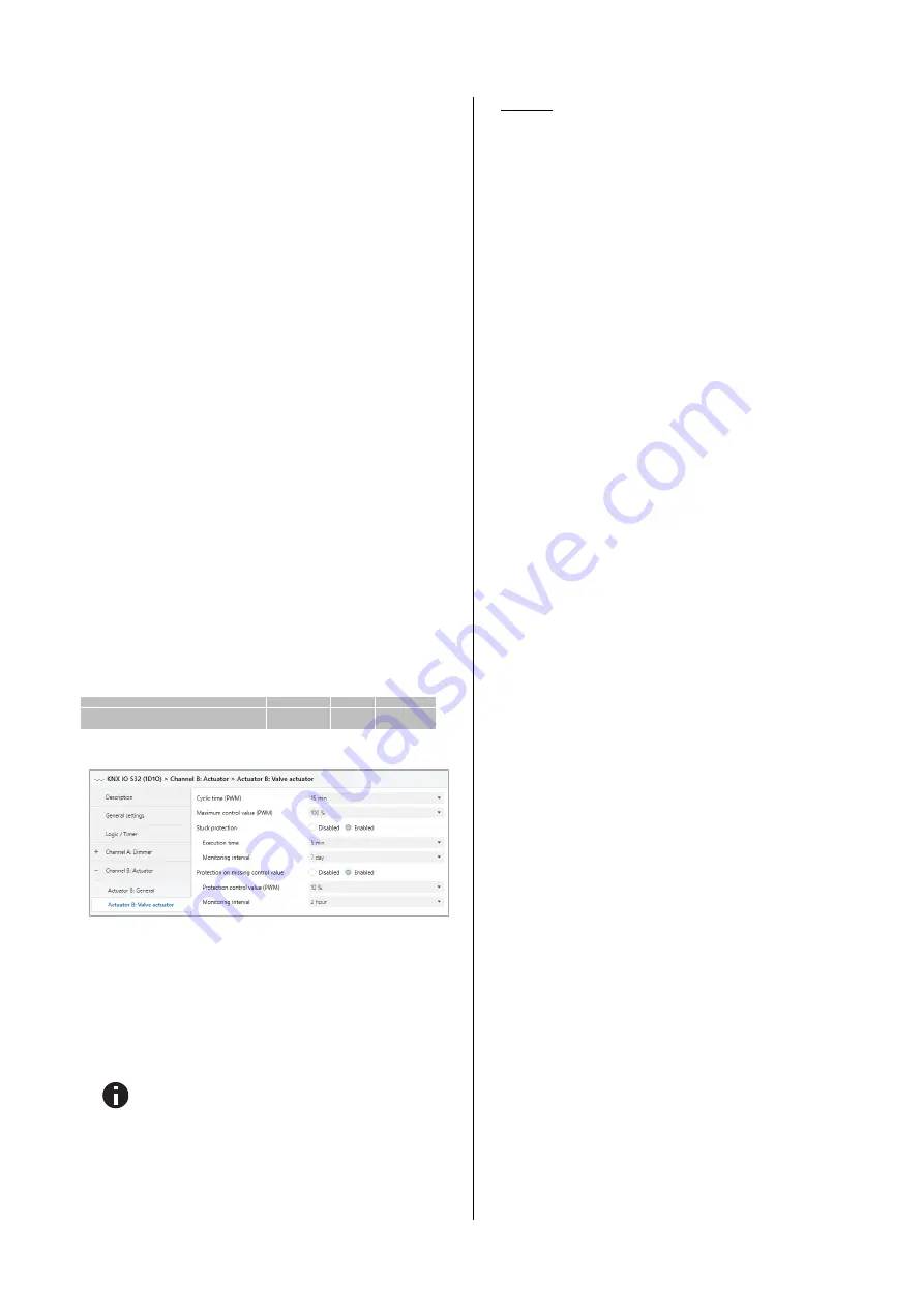
If the valve actuator is selected on the parameter page "Actuator
B: General", a group object for the valve actuator appears in-
stead of the normal switching object. This allows the current
PWM at the output to be set via KNX (0% - 100%). An additional
parameter page "Actuator B: Valve actuator" appears for the
configuration of the valve actuator.
The received control value is saved automatically by the device,
to continue faultless after a possible bus power loss.
Group object
Type KNX
Size
Direction
GO 74 Actuator B: Valve actuator (PWM)
- Control value
5.001
1 Byte
From KNX
P.
Actuator B: Valve actuator
Cyclic time (PWM)
The cyclic time of the PWM, which is used to control a servo
drive, is configured with this parameter. One cycle involves a
time range in which the output is switched on and one in which
the output is switched off. The cyclic time corresponds to the
period between two rising edges (state change at the output
from OFF to ON). The longer the flow of the heating circuit (tube
/ pipe length), the higher the cyclic time should be set.
Typical thermal servos require several minutes for a
100% valve change.
Maximum control value (PWM)
This parameter can be used to limit the maximum control value.
The control value is expressed in percent and de-fines the period
during which the output is switched on in one cycle.
Example
:
Cyclic time = 10 Min.
Maximum control value (PWM) = 80 %
Maximal output state = ON - 8 min / OFF - 2 min
Stuck protection
With the stuck protection, it is intended to prevent the valve from
being damaged by corrosion or calcification, that it can no longer
be moved. In case stuck protection is enabled, this is only trig-
gered if the value is permanently 0 % or 100 %. On every other
control value the servo already moves, so there is no need for a
stuck protection.
Control value 0%
Open servo for the set time
Control value 100%
Close servo for the set time
In case the valve is not allowed to open, the stuck protection
must be disabled.
Execution time
If the stuck protection is activated, this parameter is used to set
the duration of the state change.
Monitoring interval
If the stuck protection is activated, this parameter sets the moni-
toring interval. If the state of the output remains un-changed for
this time, the lock protection is triggered.
Protection on missing control value
This parameter enables the protection function on missing con-
trol value telegrams. This is necessary in order to prevent un-
wanted and uncontrolled overheating or cooling down of the
room, when the control value is missing.
Protection takes effect, as soon as no telegrams are received
from the controller over a longer period of time. As soon as this
extended telegram pause has occurred, it can be assumed that
the corresponding controller has failed or the connection be-
tween the controller and the valve actuator has been interrupted.
Protection control value (PWM)
If the protection on missing control value is enabled, this pa-
rameter sets a protection control value. This configured PWM
value will set the output, if the protection is active.
As soon as telegrams from the controller are received again, the
protection control value (PWM) is overwritten by the received
value. The protection does not react again, until the waiting time
in the set monitoring interval is exceeded between individual
telegrams.
Monitoring interval
If the protection on missing control value is enabled, this pa-
rameter sets the monitoring interval. If no further telegram is
received by the device during this time, the protection function
takes effect.
Lock function (with valve actuator)
With this parameter the lock function can be disabled or enabled.
If this functionality is activated, the associated group objects as
well as the parameter page “Actuator 1: Lock function” are dis-
played for further configuration. If the lock has been activated via
the group object "Lock", the received switching telegrams are not
executed.
In addition to the lock object, there is also a priority object, which
can be used to set a control value independently of the lock.
Thus, it is possible to set an output PWM without affecting other
functions.


