


63899-002 Rev. A 3/20/2024
38
easily be added into the system. The LMV3 compatible part number for purchase is
1000185-KIT
. For
wiring a UV scanner into the control, please reference the LMV3 Technical Instructions link and QR
code found on Page 39. It is important to note that the sight glass must be removed when the UV kit is
installed. There will be no flame signal detected if the glass remains in place.
D: TROUBLESHOOTING
The most common fault codes have been noted below. For all LMV3 fault codes and diagnostic codes please
refer to the LMV3 Technical Instructions below on page 39. A QR code and a URL link have been provided for
a full electronic copy on Page 39.
TABLE 4: COMMON FAULT CODES
Error
Code
(Loc:c:)
Diagnostic
Code
(Loc:d:)
Meaning
Corrective Action
2
Any #
No flame at end
of safety time
A flame failure occurred during lighting.
1. Check the wiring of the ignition transformer, pilot valve, and main valve(s).
2. Check manual shutoff valves for supply gas.
3. Check the position of the air damper and close it further if necessary.
4. Check the flame detector signal in the presence of a known flame source.
Replace the flame detector if it does not produce the anticipated signal.
3
0
Air Pressure Off
The air pressure switch input was de-energized when it should have been energized.
Make sure the blower starts in phase 22 and the switch setpoint is set appropriately.
1
Air Pressure On
The air pressure switch input was energized when it should have been deenergized.
Make sure the blower turns off in phase 78 and the switch setpoint is set appropriately.
If necessary, increase the setting of parameter 213.
4
Air Pressure On
Prevention of
Startup
The air pressure switch input is energized, preventing the LMV3 from starting up.
7
Any #
Loss of flame
1. Increase the setting of parameter 186:01 (fuel 0) or 187:01 (fuel 1). This increases
the FFRT. A maximum setting of 30 equals a 4 second FFRT.
2. Check the flame detector signal in the presence of a known flame source. Replace
the flame detector if it does not produce the anticipated signal.
20
Any #
Gas Pressure
Switch (Min)
1. A fault occurred related to the low gas pressure switch. See diagnostic codes for
more information.
2. The low gas pressure switch (input X5-01.2) opened, causing a fault. Check gas
supply and open any manual shutoff valves. Check the setpoint and wiring of the low
gas pressure switch.
3. The low gas pressure switch was not made by the end of phase 22, preventing the
startup of the LMV3. See diagnostic code 0 for more corrective actions.
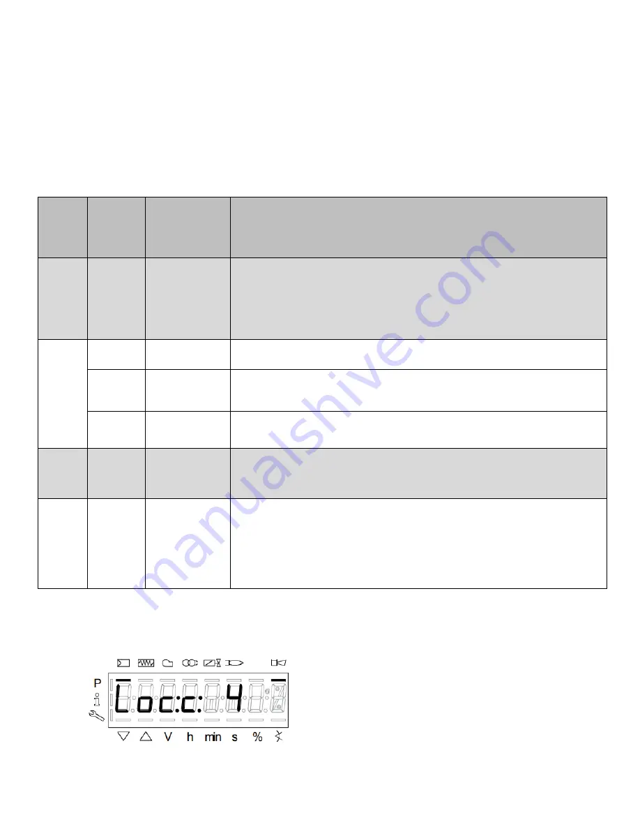
D.1 DISPLAY OF FAULTS
The example shown below displays error code 4, diagnostic 3. Refer to the LMV Manual for a
comprehensive list of fault codes.
Loc:c:
This display shows the current
fault status.
Содержание LC2300M
Страница 35: ...63899 002 Rev A 3 20 2024 35 B WIRING DIAGRAM...
Страница 36: ...63899 002 Rev A 3 20 2024 36...
Страница 57: ...63899 002 Rev A 3 20 2024 57...
Страница 58: ...63899 002 Rev A 3 20 2024 58...
Страница 59: ...63899 002 Rev A 3 20 2024 59...
Страница 60: ...63899 002 Rev A 3 20 2024 60...
Страница 63: ...63899 002 Rev A 3 20 2024 63 This page intentionally left blank...
Страница 64: ...63899 002 Rev A 3 20 2024 64 NOTES...