


63899-002 Rev. A 3/20/2024
37
C: FLAME SENSING WITH EQUIPPED CONTROLS
UTILIZING FLAME ROD SENSING
The Siemens LMV3 controls equipped with flame rod sensing utilize the flame current rectification
principle for main burner flame sensing. The burner is factory programmed to “High Sensitivity”
(Parameter 197 = 1 and Parameter 198 = 2) to ensure the best flame sensing performance.
The flame rectification phenomenon occurs as follows: The ignited gas flame causes the immediate
atmosphere around the flame to become ionized (gas atoms become electrically charged). The
ionization causes the atmosphere around the flame to become electrically conductive. An AC voltage
output from the control sensing circuit is routed through the flame sensor probe. When the sensor
probe and the burner head are both in contact with a properly adjusted flame, the burner head with its
larger surface attracts more free electrons, thus becoming negatively charged. The sensor probe with its
small surface area gives up free electrons, thus becoming positively charged. The free electrons from
the AC voltage in the sensor probe flow through the ionized gas flame to the grounded burner head. As
the AC current passes through the gas flame, it is rectified into a DC current flowing back to the
grounded side of the sensing circuit. The flame is a switch. When the flame is present, the switch is
closed allowing current to flow through the sensing circuit of the control. When no flame is present,
the switch is open with no current flowing through the sensing circuit of the control.
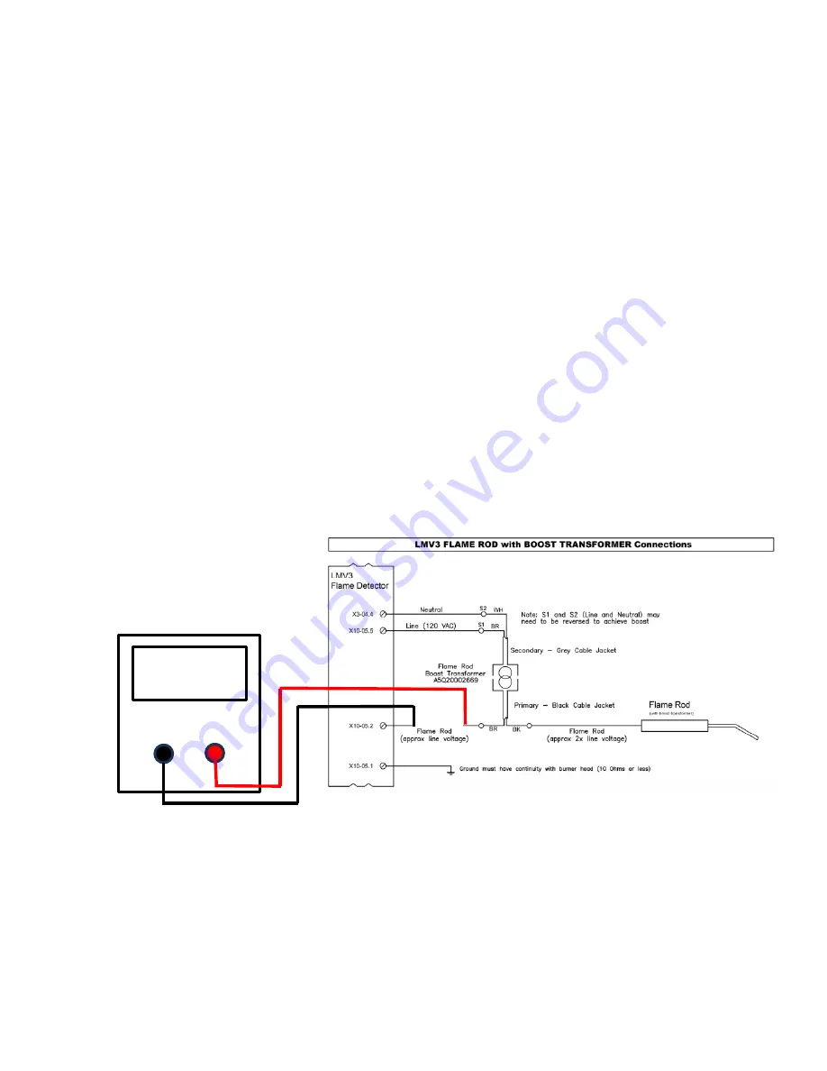
The DC current flow is measured in units called DC microamperes. A steady DC microampere current
of 2.3 minimum (and steady) or higher through the sensing circuit of the primary ignition control is
sufficient to keep the burner running without a safety lockout. See Figure 21 in SECTION V –
TECHNICAL INFORMATION for sensor probe and electrode dimensional settings and Figure 12 for
flame current measurement.
Flame Current Measurement
Figure 12
FLAME SENSING USING A UV SCANNER
An ultra-violet (UV) scanner is sometimes used with a flame safeguard. The UV scanner senses the
presence of flame by viewing the ultra-violet light emitted by the flame. A flame safeguard conducts a
check of the UV scanner during each ignition sequence. Prior to opening the gas valves, the flame
safeguard will verify a “no flame” signal from the scanner. A UV scanner is not provided, but can
Micro-amp Scale
2.3µA DC Min
and Steady
Содержание LC2300M
Страница 35: ...63899 002 Rev A 3 20 2024 35 B WIRING DIAGRAM...
Страница 36: ...63899 002 Rev A 3 20 2024 36...
Страница 57: ...63899 002 Rev A 3 20 2024 57...
Страница 58: ...63899 002 Rev A 3 20 2024 58...
Страница 59: ...63899 002 Rev A 3 20 2024 59...
Страница 60: ...63899 002 Rev A 3 20 2024 60...
Страница 63: ...63899 002 Rev A 3 20 2024 63 This page intentionally left blank...
Страница 64: ...63899 002 Rev A 3 20 2024 64 NOTES...