


63899-002 Rev. A 3/20/2024
18
H.1 BURNER HEAD ADJUSTMENT:
From Tables 1 and 2, find the Burner Head Setting (Dimension “A”) for the desired flow rate at
which the burner will be operating. Referencing Figure 8, adjust the burner head by loosening
the both the jam nut that locks the burner head adjusting screw and the black nut along the side
of the burner. Without loosening the nut along the side, the adjustment screw mounting bracket
is likely to break.
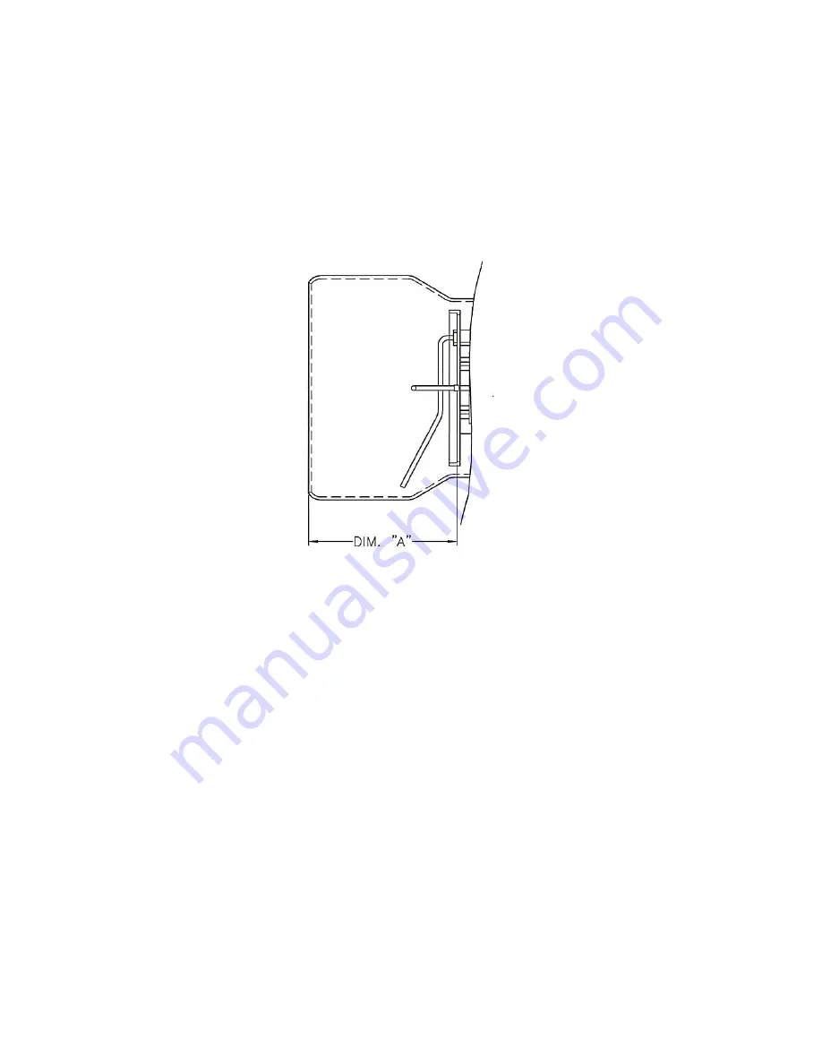
Using a 5mm Allen wrench, adjust the burner head while measuring from the end of the air
tube to the front of the burner head, referencing Figure 7. Once Dimension “A” is achieved, re-
tighten the jam nut.
Burner Head Setting Dimension “A”
Figure 7
NOTE: BURNER HEAD SETTING WILL FACTORY SET ‘DIM A’ BETWEEN 3”
AND 3.25”. BASED ON APPLICATION, FURTHER SCREW ADJUSTMENT MAY BE
REQUIRED TO ADJUST FLAME SHAPE (REFERENCE FIGURE 8). THE LARGER
THE HEAD SETTING, THE SHORTER AND BUSHIER THE FLAME. THE
SMALLER THE SETTING, THE LONGER AND LEANER THE FLAME.
Содержание LC2300M
Страница 35: ...63899 002 Rev A 3 20 2024 35 B WIRING DIAGRAM...
Страница 36: ...63899 002 Rev A 3 20 2024 36...
Страница 57: ...63899 002 Rev A 3 20 2024 57...
Страница 58: ...63899 002 Rev A 3 20 2024 58...
Страница 59: ...63899 002 Rev A 3 20 2024 59...
Страница 60: ...63899 002 Rev A 3 20 2024 60...
Страница 63: ...63899 002 Rev A 3 20 2024 63 This page intentionally left blank...
Страница 64: ...63899 002 Rev A 3 20 2024 64 NOTES...