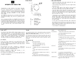
Appendix L – Connectors and Indicators
SPS-5 v
9
Dual
Com Port System:
LED Indicators:
POWER:
GREEN LED
– Shows Power is Applied
RF TX:
GREEN LED
– Shows Transmission of Page
RF CD:
GREEN LED
– Shows Carrier Detect
DATA 1:
GREEN LED
– Port 1 RS-232 Cable is Attached
DATA 2:
GREEN LED
– Port 2 RS-232 Cable is Attached
PROGRAM:
RED LED
– Shows when In/Out of
Programming Mode and Rebooting System and it also
lights up if an Error is found within the Encoder System.
RS-232 DB-9 Connector Pin-Out:
(Both Ports)
1 CD
(not used)
2
RD
(data output by paging encoder, typically required)
3
TD
(data received by paging encoder, required)
4
DTR
(not used)
5
GND
(required)
6
DSR
(signal output by paging encoder, requirement
depends on host system)
7
RTS
(signal input to paging encoder, required only if
hardware flow control mode is active)
8
CTS
(signal output by paging encoder, required only if
hardware flow control mode is active)
9
RI
(not used)
“The v9
S Single
Com Port System” is: Next Page


