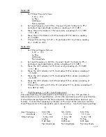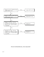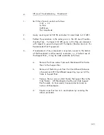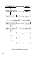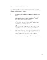
Model 452
1 .
Set fi l ter settings as fol l ows:
5 . 00 x 1 00
La Pass
o
dB Gain
F lat Ampl itude
2 .
Set input frequency to 500 Hz . Connect the AC Voltmeter to TP-1
and adjust input ampl itude to obtain a reading of -1 0 . 0 dBV .
3 .
Move the A C Voltmeter to T P-2 and verify a reading of -1 4 . 1 dBV
( ± O . l dB l .
4 .
Move the AC Voltmeter t o OUT and adjust R1 9 to obtain a reading
of -4. 8 dBV .
5 .
Change fi lter setting to 5 . 00
x l
K and adjust R1 1 to obtain a reading
of -1 . 8 dBV at OUT.
Mode l 852
1 .
Set fi l ter settings as fol l ows:
5 . 00 x 1 00
La Pass
o
dB Gain
F l at Ampl itude
2 .
Set input frequency to 500 Hz . Connect the AC Vol tmeter to TP-1
and adjust input ampl itude to obta i n a reading of -1 0 . 0 dBV .
3 .
Move the AC Voltmeter to T P-2 and verify a reading of -1 5 . 5 dBY
( ± 0 . 1 dB l .
4 .
Move the AC Voltmeter to T P-3 a nd adjust R1 9 to obtain a reading of
-1 7 . 4 dBV .
5 .
Move the AC Voltmeter to T P-4 and adjust R24 to obtain a reading of
-1 2 . 8 dBY .
6 .
Move the AC Voltmete, to OUT and adjust R31 to obtain a reading of
+3 . 6 dBV .
7 .
Change fi l ter setting to 5 . 00 x l K and adjust R1 1 to obtain a reading of
+6 . 6 dBV at OUT .
d .
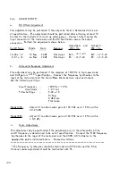
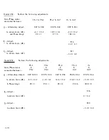
High Frequency ( x 1 0K ) Cutoff Adjustment
This adjustment may
performed if cutoff frequency i n the x 1 0K position is
determined to be out of specification, whi l e other positions are within specificatio n .
I t shoul d a l s o be performed i f the G a i n adjustment described above has been per
formed . Connect the Frequency Synthesizer to the input of the instrument and the
Gain/Phase meter to the appropriate points shown bel ow . Use the fol l owing settings
A
B
C
Input Frequency
50 . 0 KHz
1 00 . 0 KHz
50 . 0 K Hz
Amplitude
1 . 0 V rms
1 . 0 V rms
1 . 0 V rms
Fi Iter Settings
5 . 00 x 1 0K
1 . 00
x
1 0K
5 . 00 x l OK
Lo Pass
H i Pass
H i Pass
o
dB Gain
o
dB G ain
o
dB Gain
Flat Ampl itude
F lat Amplitude
F lat Ampl itude
4- 17


