4-8
f.
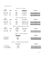
Harmoni c Components
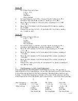
Because of the extre me l y l ow distortion of these i nstruments, a special measure
ment procedure must be employe d . The arrangement shown in Setup # 4 is re
commended . Here , the unused channel of the instrument is employed as a Low
Pass F i l ter to reduce the harmoni c components of the 5 1 00 Frequency Synthesizer
to leve l s of -1 00 dB or l ess . The output of the Channe l U nder Test (CUT) is
viewed on the 3580 A S pectrum A na l yzer direct l y , or through a possive Notch
F i l ter centered on the measurement frequency . For the va l ues shown, the Notch
Fi I ter w i l l attenuate the fundamental ( 1 K Hz ) by at least 50 dB, whi Ie the
2nd hanmoni c is attenuated 1 0 dB and the 3rd harmonic
6
dB .
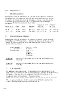
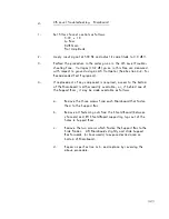
Set the Synthesizer frequency to 1 . 000 KHz and the Low Pass Filter to a Cutoff
Frequency of 1 . 00 x l K , 0 d B Gain, Flat Ampl . response . Set the Channel
Under Test as fol l ows:
1 . 00 x 1 0 Cutoff Frequency
Hi Pass
20 dB G a i n
F l at Ampl .
Increase Synthesizer ampl itude unti l ful l -sca l e signal of 7 . 1 V rms ( + 1 7 dBV )
appears at the output of the C U T .
Connect the 3580 A Spectrum Ana l yzer to the output of the C U T a n d set its
contro l s as fol lows:
Bandwidth
Freq . S pon
Sweep Time
D isplay
Input Sensitivity
I n put Sensitivity Vernier :
3 0 Hz
.5 KHz/div
1 sec/div
L OG , 1 0 dB
+
1 0 dBV
A d j ust to obtain ful l -scale (0 dB) D isplay
a t 1 K Hz .
Amplitude Ref Level
Normal
Connect the S pectrum Anal yzer to the output of the Notch Fi lter and increase
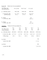
Input Sensitivity to -30 dBV . Read the amplitude of each harmonic component
displayed on the screen . Harmonic Components at the oui put of the CUT with
respect to ful l -sca l e signal are cal cul ated as fol lows :
2nd Hanmonic
=
-(40 d B + 2nd Harm . Displ ay dB)
+
1 0 dB
3rd Hanmonic
=
-(40 dB + 3rd Harm . Display dB)
+ 6
dB
4th Harmonic
=
-(40 dB + 4th Harm . Displ ay dB) + 4 dB


