4-6
b .
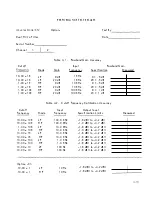
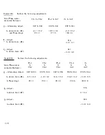
Cutoff Frequency Cal i bration Accuracy (See Fig . 4-3)
With the equi pment connected as shown i n Setup # 1 , set CUT gain to 0 dB
and the Frequency Synthesizer output to 0 . 0 dBV . At each Cutoff Frequency
setting shawn i n Tab le 4 . 2 set the Synthesizer frequency equa l to the Cutoff
Frequency setting .
The ± 2% specifi cation on Cutoff Frequency Cal i bration A ccuracy is met i f
the output l evel fal ls within the tolerance l i m its shown i n Fig . 4-3, name l y :
Model 452
-3dBV ± 0.6 dB
( -3dBV ± 0 . 85dB , i n
x
1 0K , H P)
Model 852
-3dBV ± 1 . 2dB
( -3dBV ± 1 .7 dB, in
x
1 OK, H P)
c .
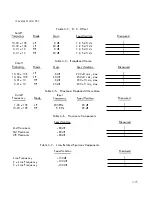
DC Offset
Connect a short across the i nput connector of the Channel Under Test (CUT) and
the DC Multimeter across the output connector. A l l ow at least 1 0 minutes for
the i nstrument to warm up under its own power and measure the DC Offset for the
settings shown i n Tab l e 4 . 3 .
.
d .
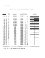
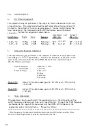
Broadband Noise
Connect equipment as shawn i n S-etup #2 . Connect a short across the i nput
connector of the Channel Under Test and set the Ground/F l oat switch on the
rear pen e l to the F l oat position . Turn off a l l unused equi pment i n the vi cinity
of the test area and disconnect it from the instrument under test.
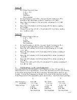
Connect the 452 Post F i l ter/Ampl ifier as a Band -Pass fi l ter with the fol l ow i ng
settings:
CH 1 : 0 . 01
x
1 0 Cutoff Frequency
H i Pass
2 0 dB Gain
F lat Ampl .
CH 2 : 1 0. 00
x
1 0K Cutoff Frequenc;
Lo Pass
20 dB Gain
F lat Ampl .


