4-5 .
TROUBLESHOOT I N G PROCED URES
a .
1 st Level Troubleshooting
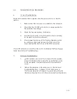
If both LED i nd icators fai l to operate when the power switch is in the ON
position:
1 .
Make certain that l ine power is avai lable to the i nstrument .
2 .
Check that the 1 1 5/230 volt switch is i n proper position for
the ava i lable l ine voltage .
3 .
Check the fuse and replace, if defective .
4 .
W ith the power switch in the O N position check continuity
of the power cord with an ohmmete r .
5 .
Check proper functioning of the F l oating Operation switch
by verifying a short/open between the third w i re of the
power cord and the she l l of one of the B N C connectors.
If one LED indicator is on and the other is off, troubleshoot the Power Supply
board (see 3rd Leve l Troubleshooti ng) .
b .
2nd Level Troubleshooting
1 .
If both i ndicators are on but the i nstrument fai l s to operate ,
remove the hardware that secures the tap and bottom covers
to the rear pane I ; sl ide back and remove top and bottom
covers .
2 .
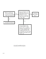
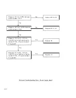
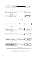
Perform the procedure i n the order given i n the 2nd Leve l
Troubleshooting Tree . Voltages (±0 . 25 Volts) given in
this Tree are measured with respect to ground using a Digital
M u l timeter (See Section
4-2
for Recom mended Test Equ i pment).
4-1 9


