d .
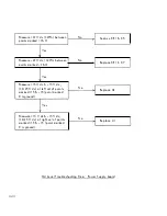
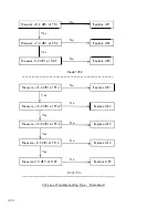
4th Level Troubl eshooting: Mainboard
1 .
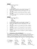
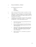
Set fi l ter channel contro l s as fol lows:
5 . 00 x
l K
La Pass
o
dB Gain
Flat Amplitude
2 .
Apply input signal at 500 Hz and adjust its amplitude to 0 . 0 dBV .
3 .
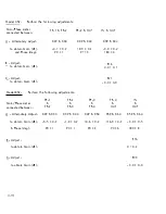
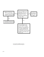
Perform the procedure in the order given in the 4th Leve l Trouble
shooting Tree . Voltages (±0 . 2 dB) given in this Tree are measured
with respect to ground using an AC Voltmeter (See Section 4-2 . for
Recommended Test Equ i pment) .
4 .
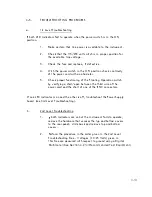
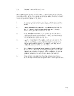
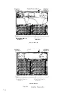
I f repl acemen t of any component i s required, access to the bottom
of the Mainboard is either readi ly avai lable , or, if behind one of
the Support B ars, it may be made avai lable as fol lows:
a .
Remove the three screws from each Mainboard that fasten
them to the Support Bar.
b .
Remove a l l fastening nuts from the Shie l d Board (between
channels) and l i ft Shield Board supporting l ugs out of the
holes in Support Bars .
c .
Remove the two screws whi ch fasten the Support Bar to the
S ide Frames . Lift Mainboards sl ightly and sl ide Support
Bar forwards (or backwards) to expose desired area on
bottom of Mainboard .
d .
Repa i r as per Section 4-6 . and re place by reversing the
above procedure .
4-23


