4-7.
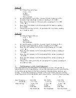
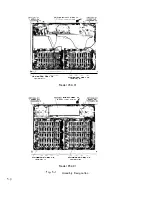
POWER SUPPLY REMOVAL
Step
1
- Remove top a nd b ottom cove rs .
Step
2 -
Remove ce nte r conducto r from al l fou r BNC c o n n ecto rs o n t he
r e a r p a n el .
Be ve ry careful not to move o r b e nd c e n t e r
c o nd ucto r .
(
I t i s ve ry s u scept i b l e to b re ak i ng ) .
Step
3
- The r ib b on cab I e comi ng ou t of the pow e r s u ppl y s h i el d s ho u l d b e
d i s c o n n ec t ed from the b oa rd s i t ' s goi ng to , n ot i ng wi r i ng con
f i gu r at i o n .
Step
4
U n s c rew the
5/16
i nch nu t to remove the pow e r swi tch from the
f ront p a n el .
Step
5
-
U n s c rew the fou r cab l e ti es on t h e s i de p a n el .
S tep
6
-
U s i ng a fl a t b l a de sc rew d r i v e r i n b e h i nd the powe r s u ppl y
s h i el d , p ry out the b l ac k " H ayco" grom me t .
Cut any cab l e t i es
.i f n e ede d .
Step
7
- R emove t h e two sc rews ho l di ng the rea r pa n el to s i d e frame a nd
t he two sc rews hol di ng the powe r s u p p l y s h i el d to r e a r p a n el
a nd l e t the panel l ay down fl a t. ( I f a n
01
o p t i o n i s i ns t� l ed ,
r emove the two sc rews fr om the r i g h t a ng l e b racket to the
s tand of f of the capa c i to r pack s
)
.
Step
8
- L i ft the powe r s u p p l y s h i el d up a nd move i t to the s i de a s muc h
a s y o u n eed t o remove the fou r s c r ew s ho I d i n g the powe r s u p pl y
b oa rd i n .
Step
9
-
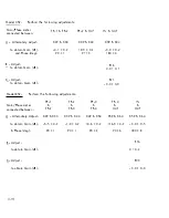
U ns o l de r the fi ve wi res from the l i ne c o rd a nd powe r swi tch co-ax
c ab l e on the powe r s u p p l y b o a rd n ot i ng wi r i ng conf i g u r a t i o n .
Step
10-
T he powe r s u p p l y b o a rd ca n now b e removed fo r repa i r o r r ep l a ceme n t .
4-26


