background image


21 


2.3.2  Cleaning Status 

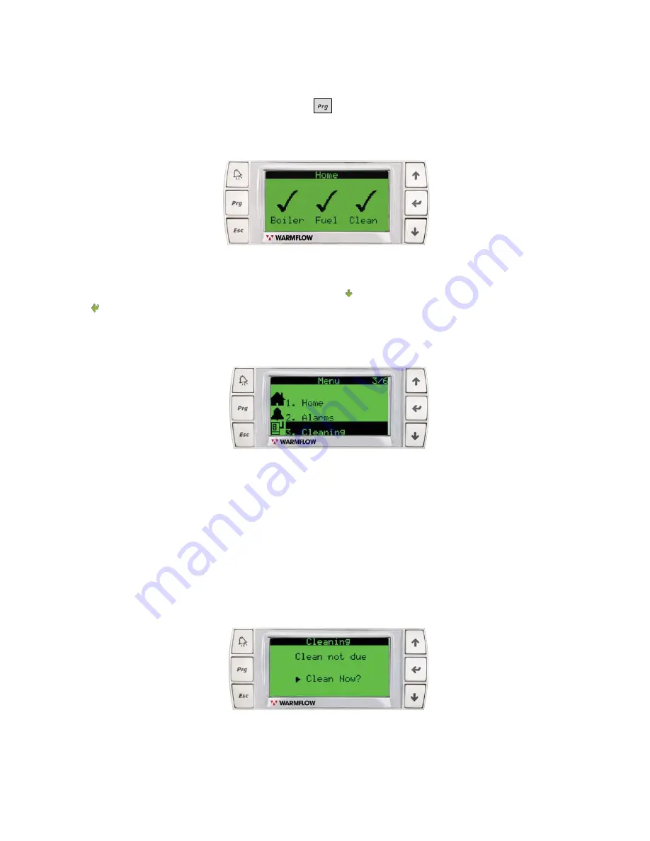
The cleaning status of the appliance can be viewed at any time. 

From the home screen (Figure 24), press the 

 ‘Program key’ to view the main menu. 


Scroll to “3. Cleaning” in the Main Menu using the


 ‘Down Arrow’ and confirm selection using 

the   ‘Enter key’. (Figure 25) 

 
The cleaning status screen should now be displayed. 
 
If  the  cleaning  status  screen  in  Figure  26  is  displayed,  a  scheduled  clean  is  not  yet  due. 
Insufficient operating hours have elapsed for the cleaning scheduler to trigger a cleaning alert.  


Figure 24: Home Screen


Figure 25: Main Menu - Cleaning


Figure 26: Cleaning Status – Not Due


Содержание WS18

Страница 1: ...8 WP18 For use with ENplus A1 wood pellets only Look for the ENplus A1 symbol Incorporating User Instructions Installation Instructions Service Record Guarantee Terms Conditions Registration Documents...

Страница 2: ...s engineer in accordance with Section 4 2 of this manual A service history must be maintained in Section 8 of this manual NI Customers Only Warmflow Engineering customer care NI provides an excellent...

Страница 3: ...ess 41 3 2 3 Heating System 41 3 2 4 Air Vents 42 3 2 5 Drain Cock 42 3 2 6 Pipework 42 3 2 7 Heating System Design 42 3 3 Sealed Systems 42 3 3 1 Expansion Vessel WS 18 Models only 42 3 4 System Fill...

Страница 4: ...MS CONDITIONS 78 7 APPLIANCE INSTALLATION COMMISSIONING CERTIFICATE REGISTRATION 82 8 APPLIANCE SERVICE RECORDS 85 9 APPENDIX A SUPPLEMENTARY INSTALLATION AND OPERATING INSTRUCTIONS FOR THE UK MARKET...

Страница 5: ...door must be kept closed at all times when not refilling The combustion door is located behind the green coloured front casing door and has an interlock fitted to ensure the door cannot be opened dur...

Страница 6: ...he ash pan will typically require emptying on a monthly basis The appliance should never be operated without the ash pan in position The ash may be discarded with garden waste or in line with local wa...

Страница 7: ...l Supply 230V Single Phase 50Hz Maximum Current Amps 5 Maximum Wattage 420 Standby Wattage 20 Performance Efficiency kW Maximum Output 18 92 9 Minimum Output 4 90 1 Fuel Type Wood Pellets Quality ENPl...

Страница 8: ...n the pellet hopper door See Figure 1 and pour in the pellets To protect the user a hopper safety guard is located in the top of the hopper beneath the pellet hopper door This must not be removed Once...

Страница 9: ...r is low The appliance will typically operate as normal for 1 hour dependant on the heat demand of the property You should fill the hopper within this time Filling the hopper will automatically reset...

Страница 10: ...scroll through the menu Confirm selection with the Enter key when the required item is highlighted in black There are six options in the main menu including Home Alarms Cleaning Engineer Settings and...

Страница 11: ...w or the Up Arrow key can then be used to scroll through the alarms Refer to Section 5 for more information on the alarm messages that can be displayed and the appropriate action to take in each case...

Страница 12: ...tant that the date and time are set correctly as shown in Figure 11 The date and time are adjusted using the Down Arrow or the Up Arrow keys Confirm with the Enter key The day will automatically updat...

Страница 13: ...appliance displayed in degrees Celsius Ambient temperature if the appliance is cold No greater than 170 C in normal operation Flow Temp The temperature of the water in the flow pipe connected to the t...

Страница 14: ...rty is cold As the temperature of the property increases the Heat Req value will decrease Draught Set Indicates the draught required to ensure correct airflow through all modes of operation displayed...

Страница 15: ...iance varies through start up modulation and shut down and can be seen changing when viewing information screen 1 see Figure 13 Further explanation of each operating mode is given in Table 4 Mode Desc...

Страница 16: ...ne of the 4 conditions listed above are present AND Holiday mode is disabled Refer to Page 18 There is a switched live signal e g from a timeclock or thermostat The flow temperature is below trigger t...

Страница 17: ...ulate down through its power bands and may eventually proceed to the Shut down sequence detailed in Figure 18 The appliance has a Shutdown sequence as shown in Figure 18 The Shutdown sequence can be p...

Страница 18: ...isk damage not the central heating system to which it is connected including the central heating pipework at the point of connection at the appliance The anti condensation valve of the appliance will...

Страница 19: ...een in Figure 19 will be displayed and normal operation of the appliance will resume Vacuum Feed Vacuum feed systems are used to transfer wood pellets from a remote pellet storage container to the hop...

Страница 20: ...igure 21 As an authorised Engineer and having entered the password the following sub menus become accessible Parameters Commissioning Engineer Servicing Working Hours History Reset Tests In Out Help S...

Страница 21: ...red When the Display Active Alarms key is pressed a cleaning alert screen will be displayed to indicate the remaining time for a clean to be completed A typical example of a cleaning alert message is...

Страница 22: ...nu using the Down Arrow and confirm selection using the Enter key Figure 25 The cleaning status screen should now be displayed If the cleaning status screen in Figure 26 is displayed a scheduled clean...

Страница 23: ...tatus will be displayed for a further three days with a daily count down indicating the remaining time before the appliance shuts down If the screen in Figure 29 is displayed the appliance has shut do...

Страница 24: ...ve cleaning may be of benefit for example where the product may be unattended when the next scheduled cleaning is due Cleaning in advance of this time will avoid the unnecessary shutdown of the applia...

Страница 25: ...when placed in contact with hot ash or combustion deposits There are 18 steps to cleaning a WS18 WP18 Wood Pellet Boiler Appliance Please complete all steps with care in order to prolong the life of t...

Страница 26: ...eaning preparation time can vary depending on the temperature of the appliance when cleaning preparation utility is initiated STEP 3 Wait for Cleaning Preparation to Complete The screen in Figure 34 w...

Страница 27: ...to release the latch The front casing door can now be opened Do NOT turn the appliance off at any stage during this procedure using the isolator switch on the front of the appliance see Figure 36 The...

Страница 28: ...be heard to release when this button is pressed Push down firmly on the combustion door handle while still holding the door release button as shown in Figure 37 Push DOWN Push DOWN Lift UP Figure 36...

Страница 29: ...hen all steps of this cleaning procedure are complete STEP 6 Clean the Combustion Shelf Use a suitable brush to remove any build up of ash dust off the combustion shelf with the combustion pot still i...

Страница 30: ...easier to remove Lift the ash pan from the ash pan area of the heat exchanger and set to the side ensuring that if hot it is not placed in contact with materials that may be affected by heat Figure 40...

Страница 31: ...suitable brush to dislodge any build up of combustion deposits from the inside of the combustion pot as shown in Figure 42 A dedicated ash vacuum cleaner may also be used Make sure the ash is sufficie...

Страница 32: ...See Figure 44 Empty any dislodged material from the combustion pot into the ash pan for a second time See Figure 41 Failure to clean the combustion pot as directed may restrict the flow of air within...

Страница 33: ...Make sure the ash is sufficiently cool before vacuuming Use a suitable brush to remove any build up of ash dust from the ash pan area of the heat exchanger A dedicated ash vacuum cleaner may also be...

Страница 34: ...STEP 12 Clean the Cleaning Knives Use a suitable wire brush to dislodge and remove any hard deposits from the uppermost surfaces of the cleaning knives as shown in Figure 48 to ensure free movement o...

Страница 35: ...this seal is removed or has become worn or damaged it should be replaced by a Warmflow engineer or other qualified biomass engineer This seal is critical for efficient operation of the appliance Loca...

Страница 36: ...on It will be difficult to close the combustion door if the ash pan is not correctly placed in the ash pan area of the heat exchanger Should you find the combustion door difficult to close return to S...

Страница 37: ...his cleaning procedure is confirmed The cleaning procedure is now COMPLETE If the screen in Figure 52 is not displayed at the end of the cleaning procedure an interruption has occurred For example the...

Страница 38: ...r by completing STEP 5 of the cleaning procedure o Close the combustion door by completing STEP 16 of the cleaning procedure o The Cleaning Confirm Screen See Figure 57 should now be displayed and com...

Страница 39: ...on 3 4 3 The installer wiring panel is located behind the green coloured front casing door Knockouts in the casing are provided at a number of locations to aid the plumbing installation Appropriate gr...

Страница 40: ...e w 10 Ash deformation temp C 1200 Ash w 0 7 Arsenic mg kg 1 Mechanical Durability w 98 0 Cadmium mg kg 0 5 Fines 3 15mm 1 0 Chromium mg kg 10 Temperature of pellets C 40 Copper mg kg 10 Net Calorific...

Страница 41: ...how to assemble these items are below Remove and retain the 1x grommet located along each lower side edge of the appliance Insert the axle through the now exposed holes Secure 1 wheel to each side of...

Страница 42: ...imum output It may be necessary to filter combustion air See Table 1 as it enters the room where the appliance is located if there is a possibility of high levels of dust or particulates Combustible m...

Страница 43: ...allation pipework is run in copper However if plastic pipe is used the last 1000mm of pipework connected directly to the appliance must be of copper All connections to the appliance must be made with...

Страница 44: ...e system pressure should be checked periodically by means of the pressure gauge at the expansion vessel The WS18 appliance comes complete with an integrated expansion vessel pressure gauge and filling...

Страница 45: ...ble plastic drainage hose The drainage hose should be connected to an internal soil stack or waste pipe an external gully hopper or soakaway It is recommended that the drainage pipe should have a mini...

Страница 46: ...nised base which allow for the pipes to exit the casing below ground level see Figure 61 and 62 below It is advised that the pipe work from the appliance to the interior of the property must be 28mm a...

Страница 47: ...as shown in Figure 58 see page 38 The other end of the cable with the RJ12 plug connects into the back of the user interface controller supplied Max 50m shielded CAT5e cable All connections are made...

Страница 48: ...qualified biomass engineer after determining the reason for failure Fuses are located adjacent to the mains supply wiring connections and protect the following circuits Fuse 1 5x20mm F 500mA 250 VAC...

Страница 49: ...long flue extension starter piece and a 500mm long flue terminal as shown in Figure 66 The supplied flue system is adequate only if the flue terminal is more than 2 3 meters from an adjacent wall or...

Страница 50: ...are used manufacturer s instructions for correct fastening support and access for cleaning must be followed NOTE An extended flue may result in a requirement for more frequent servicing and flue clean...

Страница 51: ...ong flue extension starter piece to its uppermost position inside the metal collar of the starter piece The use of lubricant can help during this step STEP 2 Lubricate the 80mm flue seal in the flue a...

Страница 52: ...engage the starter piece Ensure the 80mm seal in the flue adapter does not become dislodged during installation STEP 4 Align the pre drilled pilot holes in the flue extension starter piece with the p...

Страница 53: ...inder STEP 6 Lower the plastic weatherproof collar until it touches the moulded top of the appliance Check that the plastic weatherproof collar is undamaged and the appliance is adequately protected a...

Страница 54: ...t screws if NOT using the plastic weather proof collar on the terminal Use the long screws if using the plastic weatherproof collar DO NOT use longer screws that would puncture the 80mm flue wall NOTE...

Страница 55: ...to nearby buildings prior to installation If a flue extension is unavoidable every effort should be made to keep the complete flue construction as short as possible and as straight as possible i e wi...

Страница 56: ...arf form cut flue sections to avoid build up of ash etc during operation of the appliance Never attempt to fabricate bespoke flue components e g bends at irregular angles from extension pieces by cutt...

Страница 57: ...ion or installation reporting this before proceeding The IP Ingress Protection rating of the product should be maintained by the use of correct cable glands and pipework grommets for installed items E...

Страница 58: ...tion shelf damper plate is correct to ensure the air gap is within tolerance as noted in Figure 77 If necessary loosen the locking screw adjust the position of the damper and tighten the locking screw...

Страница 59: ...P 4 Assignment of Required Parameters To ensure correct operation of the unit several site specific parameters must be assigned to the appliance via the Engineer menu of the user interface controller...

Страница 60: ...gure 80 using the Up Arrow key and Down Arrow key and then the Enter key to advance to the next character Press the Enter key to confirm Select 1 Parameters using the Enter key as shown in Figure 81 F...

Страница 61: ...to system check unless the flow temperature is below trigger temperature Refer to the start up sequence shown in Figure 16 Trigger temperature is selected automatically and varies depending on the fl...

Страница 62: ...mbustion but may be useful in the event of a lambda sensor fault Disable PL No This allows the low pellet level sensor to be disabled in situations where a another method is used for monitoring pellet...

Страница 63: ...speed remains within tolerance of a pre set target Auger mode range 0 26 Table 10 Description of Engineer Parameters Screen 3 Text Default value Description Unit Serial No 00000000 This is where the...

Страница 64: ...el regulation feature is to automatically select the correct auger mode to achieve the target intake fan speed of 7700rpm in Powerband 5 The following 3 scenarios can occur during operation 1 The appl...

Страница 65: ...view the main menu Scroll to 5 Engineer in the Main Menu using the Down Arrow and confirm selection using the Enter key Figure 87 Insert the engineer password into the engineer password screen Figure...

Страница 66: ...r piece See Figure 66 Remove the M10 threaded plug and insert the analyser probe IMPORTANT Testing while the appliance is still relatively cold gives inaccurate results and leads to incorrect adjustme...

Страница 67: ...e of installation and 90 days from the date code stamped on the appliance A copy of this certificate should remain with the appliance householder STEP 8 User introduction to the appliance A correctly...

Страница 68: ...or to the start of the heating season 4 3 Flue Cleaning It is extremely important especially in the case of extended flues to have all internal surfaces of the complete flue system cleaned during serv...

Страница 69: ...s in the following pages suggest possible causes for the activation of each alarm Suggested actions for each alarm condition are also included The suggested actions are attributed to the user typicall...

Страница 70: ...Servicing must be conducted by a Warmflow engineer or other competent engineer who has received appropriate training Air is trapped in the heating system creating steam inside the top of the heat exc...

Страница 71: ...temperature sensor is faulty Clean the appliance following the cleaning procedure detailed in Section 2 5 3 Service the Appliance Test the operation of the flue gas temperature sensor and re connect r...

Страница 72: ...h enough pellets to cover the pellet level sensor Test the operation of the pellet level sensor and repair replace if necessary Blockage restricting fan rotation Intake fan faulty power supply wiring...

Страница 73: ...e pellet hopper door and repair replace if necessary The combustion door has been left open The combustion door switch is faulty The combustion door handle and locking mechanism is faulty Close the co...

Страница 74: ...is faulty or disconnected Ensure the clear 6mm ID hoses are not damaged and are connected to the correct ports on the pressure sensor Replace hoses if necessary Test the operation of the pressure sens...

Страница 75: ...g The exhaust fan is faulty and the draught act value is not matching the draught set The pressure sensor is faulty Follow the instructions on the screen Wait for the counter on the screen to reach 0...

Страница 76: ...l delivery system The temperature of the appliance has exceeded a high limit value This alarm must be assessed further by a Warmflow engineer or other qualified biomass engineer The water pressure in...

Страница 77: ...e property heat demand has still not been satisfied Flow temperature set too low in user menu Temperature Airlocks in heating system Auger mechanism fault Anti condensation valve fault Anti condensati...

Страница 78: ...s are getting damp in the hopper Check for water ingress points around hopper door and flue Rectify water ingress replace pellets Noise in heating system when appliance is operating Water flow rate to...

Страница 79: ...installation and any other conditions of this warranty are met Please note that periods of guarantee will not be extended under any circumstances Warmflow s Obligations Where components are found to...

Страница 80: ...ter the date of installation and thereafter at twelve 12 monthly intervals or sooner if required by the variable service schedule in the controller Warmflow reserves the right to determine at its abso...

Страница 81: ...e other than an authorised service provider carry out works to your Boiler this warranty will automatically become null and void Other property In no event shall Warmflow have any liability or respons...

Страница 82: ...the improper use or storage of the boiler and in particular but without limitation Warmflow shall not be liable in the case of defects arising from normal deterioration or improper or faulty handling...

Страница 83: ...ibly Ensure that the certificate is signed by both the Competent Person and the Customer Carbon copies of the certificate are produced automatically Register the Appliance Remove the white copy of the...

Страница 84: ...n Date Fuel Brand ENplus 1 CO2 Concentration Boiler Parameters See Section 4 of the product manual CO Concentration ppm Fuel Alarm Mins Water Press NO NC O2 Concentration Pump Diff C Mode 1 On Off Flu...

Страница 85: ...84 INTENTIONALLY LEFT BLANK...

Страница 86: ...rd sheets by the Warmflow or other qualified biomass engineer conducting the service Service records must be retained for inspection upon request by the manufacturer All product warranties will be inv...

Страница 87: ...e Last Service Have there been any modifications made to the heating system since the last service For example additional radiators additional domestic hot water needs addition of auxiliary heat sourc...

Страница 88: ...e Last Service Have there been any modifications made to the heating system since the last service For example additional radiators additional domestic hot water needs addition of auxiliary heat sourc...

Страница 89: ...e Last Service Have there been any modifications made to the heating system since the last service For example additional radiators additional domestic hot water needs addition of auxiliary heat sourc...

Страница 90: ...e Last Service Have there been any modifications made to the heating system since the last service For example additional radiators additional domestic hot water needs addition of auxiliary heat sourc...

Страница 91: ...e Last Service Have there been any modifications made to the heating system since the last service For example additional radiators additional domestic hot water needs addition of auxiliary heat sourc...

Страница 92: ...e Last Service Have there been any modifications made to the heating system since the last service For example additional radiators additional domestic hot water needs addition of auxiliary heat sourc...

Страница 93: ...e Last Service Have there been any modifications made to the heating system since the last service For example additional radiators additional domestic hot water needs addition of auxiliary heat sourc...

Страница 94: ...e Last Service Have there been any modifications made to the heating system since the last service For example additional radiators additional domestic hot water needs addition of auxiliary heat sourc...

Страница 95: ...e Last Service Have there been any modifications made to the heating system since the last service For example additional radiators additional domestic hot water needs addition of auxiliary heat sourc...

Страница 96: ...ce Last Service Have there been any modifications made to the heating system since the last service For example additional radiators additional domestic hot water needs addition of auxiliary heat sour...

Страница 97: ...96 9 APPENDIX A SUPPLEMENTARY INSTALLATION AND OPERATING INSTRUCTIONS FOR THE UK MARKET...

Страница 98: ...ilding Control approval or is installed by a Competent Person registered with a Government approved Competent Persons Scheme HETAS Ltd operate such a Scheme and a listing of their Registered Competent...

Страница 99: ...oiler runs at high efficiencies the temperature of the flue gases is at times lower than conventional solid fuel appliances Although it is not classed as a condensing appliance the low flue gas temper...

Страница 100: ...stion air supply Adequate provision e g easily accessible soot door or doors must be provided for sweeping the chimney and connecting fluepipe Hearth The hearth should be able to accommodate the weigh...

Страница 101: ...3 Code of Practice for low temperature hot water heating systems of output greater than 45kW where appropriate Electrical connections The installation of any electrical services during the installatio...

Страница 102: ...e kept clean at all times IMPORTANT NOTES General Before lighting the boiler check with the installer that the installation work and commissioning checks described above have been carried out correctl...

Страница 103: ...of time then it should be given a thorough clean to remove ash and unburned fuel residues Empty the hopper of unburned fuel To enable a good flow of air through the appliance to reduce condensation an...

Страница 104: ...Remember also that during the main heating season the cleaning interval will shorten as the load on the boiler will be higher Recommended fuels The boiler is designed to burn only specialized either c...

Страница 105: ...104 10 APPENDIX B CUSTOMER CONNECTION WIRING SCHEMATIC...

Страница 106: ...105...

Страница 107: ...accurate at the date of printing E OE but will be superseded and should be disregarded if specifications and or appearances are changed in the interests of continued product improvement CODE 4341 ISS...

Отзывы: