WAGO-I/O-SYSTEM 750 XTR
System Description 27
750-352/040-000 FC ETHERNET G3 XTR
Manual
Version 1.3.0
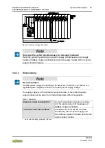
Figure 7: System Voltage (Example)
Pos: 19.16.16 /Seri e 750 ( WAGO-I/O-SYSTEM)/Systembeschr eibung/Versorgung/Systemversorgung - Anschluss - Hi nweis: Gl eichz. R ücksetzen aller Versorgungsmodul e @ 3\mod_1232950097906_21.docx @ 26760 @ @ 1
Only reset the system simultaneously for all supply modules!
Reset the system by switching the system supply simultaneously at all supply
modules (fieldbus coupler/controller and potential supply module with bus power
supply) off and on again.
Pos: 19.16.17 /Seri e 750 ( WAGO-I/O-SYSTEM)/Systembeschr eibung/Versorgung/Systemversorgung - Ausl egung @ 3\mod_1232950104812_21.docx @ 26780 @ 4 @ 1
3.6.3.2 Dimensioning
Recommendation
A stable power supply cannot always be assumed. Therefore, you should use
regulated power supplies to ensure the quality of the supply voltage.
The supply capacity of the fieldbus coupler/controller or the internal system
supply module can be taken from the technical data of the components.
Table 5: Alignment
Internal current consumption
*)
Current consumption via system voltage
(5 V for electronics of I/O modules and
fieldbus coupler/controller).
Total current for I/O modules
*)
Available current for the I/O modules.
Provided by the bus power supply unit.
See fieldbus coupler/controller and internal
system supply module
*)
See current catalog, manuals, Internet
Pos: 19.16.18 /D okumentation allgemein/Gliederungselemente/---Sei tenwechsel--- @ 3\mod_1221108045078_0.docx @ 21810 @ @ 1


