WAGO-I/O-SYSTEM 750 XTR
Fieldbus Communication 173
750-352/040-000 FC ETHERNET G3 XTR
Manual
Version 1.3.0
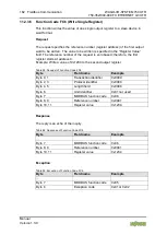
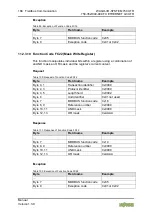
Reading the Minimum Trigger time (Register 0x1004) reveals whether a
watchdog fault occurred. If this time value is 0, a fieldbus failure is assumed. The
timer of watchdog can manually be reset, if it is not timed out, by writing a value
of 0x1 to the register 0x1003 or to the Restart Watchdog register 0x1007.
After the watchdog is started, it can be stopped by the user via the Watchdog
Stop register (0x1005) or the Simply Stop Watchdog register (0x1008).
Pos: 94.32 /Serie 750 ( WAGO-I/O-SYST EM)/Funkti onsbeschrei bung/F eldbuskommuni kation/M ODBU S/Z ugriff auf R egister werte - Watchdog-Register T abell en 0x1000 ( ALLE AUSSER 342, 842) @ 8\mod_1278923916162_21.docx @ 59540 @ 4 @ 1
11.2.5.3 Modbus
Watchdog Register
The watchdog registers can be addressed analogously with the described
Modbus function codes (read and write). Instead of the address of an I/O module
channel, the respective register address is therefor specified.
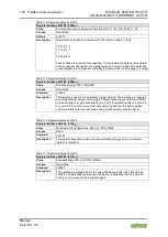
Table 112: Register Address 0x1000
Register address 0x1000 (4096
dec
)
Value
Watchdog time, WS_TIME
Access
Read/write
Default
0x0064
Description
This register stores the watchdog timeout value as an unsigned 16 bit value. The
default value is 0. Setting this value will not trigger the watchdog. However, a
non zero value must be stored in this register before the watchdog can be
triggered. The time value is stored in multiples of 100ms (e.g., 0x0009 is .9
seconds). It is not possible to modify this value while the watchdog is running.
Pos: 94.33 /Serie 750 ( WAGO-I/O-SYST EM)/Funkti onsbeschrei bung/F eldbuskommuni kation/M ODBU S/Z ugriff auf R egister werte - Watchdog-Register ( ab 0x1001 bis 0x100A) mit (R) @ 8\mod_1278926087850_21.docx @ 59546 @ @ 1
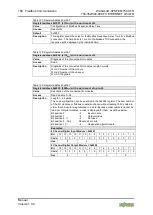
Table 113: Register Address 0x1001
Register address 0x1001 (4097
dec
)
Value
Watchdog function coding mask, function code 1...16, WDFCM_1_16
Access
Read/write
Default
0xFFFF
Description
Using this mask, the function codes can be set to trigger the watchdog function.
The function code can be selected via a "1"
FC 1 Bit 0
FC 2 Bit 1
FC 3 Bit 2
FC 4 Bit 3
FC 5 Bit 4
...
FC 16 Bit 15
Changes to the register value can only be made if the watchdog is deactivated.
The bit pattern stored in the register defines the function codes that trigger the
watchdog. Some function codes are not supported. For those the watchdog will
not be triggered even if another Modbus
device transmits one of them.
When switching the watchdog type from "Standard" to "Alternative", the coding
mask is reset to default value 0xFFFF.


