28
vc:,rtax
5. Now the, CPU adapter (It also Is In the anl11tatlc bai In which Golden Gate
was) 11 ln1t11led. The CPU adapter must be pluiied under the 68000 CPU
of the Amlea 2000. In order to do so the 68000 CPU must be pulled out of
Its socket and be plugged Into the CPU adapter. Then this module is
plutlied back
Into the 68000 socket of the
Amlea
2000.
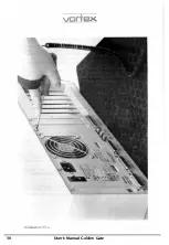
In order to reach the 68000 CPU without any problems the metal
supporting frame taking up the power supply and the floppy disk drives
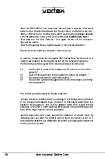
must be removed. For that 3 screws on the front of the metal supporting
frame and 2 screws on Its back must be removed with the Phillips head
screwdriver (with some versions of the case the number of screws can
vary). The various cables leading from the components fitted on the metal
supporting frame to the Amiga 2000 motherboard may on no account be
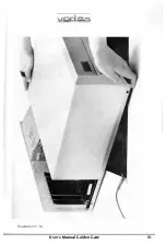
disconnected. When all screws are removed, the metal supporting frame
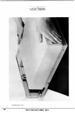
can be lifted with both hands and be tilted to the left, so that it comes to
lie on the Amiga case in the area of the slots in a head-down-position.
Directly on the right of the processor slot (into which e.g. accelerator cards
can be plugged) the 68000 CPU is located, a component of about a size of
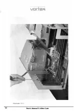
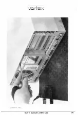
7.5cm • 2.5cm with 64 pins in its socket. The 68000 CPU can be extracted
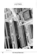
from its socket with the help of the Flat-nosed screwdriver (see illustration
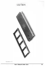
3.3.e). Then the CPU is plugged firmly and level into the CPU adapter. This
has to be done in a way to get the notch of the CPU adapter (a semicircle
gap) to lie exactly under the notch of the 68000 CPU. Afterwards this
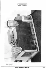
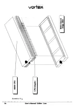
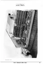
module, consisting of 68000 CPU and CPU adapter, is plugged into the
empty 68000 socket of the Amiga 2000 motherboard. In doing so take care
that the notch of the 68000 CPU socket points in the same direction as the
notches of the 68000 CPU and the CPU adapter and that all pins are neatly
fitted In the 68000CPU socket (not bent inwards or outwards). (See
lllustrations 3.3.f and 3.3.g).
6. Before the
Amiga
is built together again a short check of the proper
functioning should be carried out.
Put the metal supporting frame back in its normal position and secure
with a screw. Connect all cables and insert a copy of the disk
Goldmine
I
Into the floppy disk drive DFO:. Switch on the computer.
User's Manual Golden Gate
Содержание Golden Gate 386SX
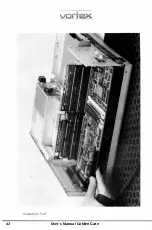
Страница 32: ...Illustration 3 3 a 30 V 1 User s Manual Golden Gate ...
Страница 33: ...Illustration 3 3 b _ s s User s Manual Golden Gate 31 ...
Страница 34: ...1 11 Illustration 3 3 c 32 User s Manual Golden Gate ...
Страница 35: ... __ lSF Illustration 3 3 d User s Manual Golden Gate 33 ...
Страница 36: ...Illustration 3 3 e 34 User s Manual Golden Gate ...
Страница 37: ...Illustration 3 3 f User s Manual Golden Gate 35 ...
Страница 38: ...C o w dQ II II II rs Ill C C a Cl Ill I I 68000CPU CPU Adapter Motherboard Amiga2000 0 i i 1 II 36 u te ...
Страница 41: ...Illustration 3 4 A _ _ User s Manual Golden Gate 39 ...
Страница 42: ...Illustration 3 4 b 40 User s Manual Golden Gate ...
Страница 43: ...Illustration 3 4 c ff r User s Manual Golden Gate 41 ...
Страница 44: ...Illustration 3 4 d 42 User s Manual Golden Gate ...
Страница 48: ...illustration 3 5 b 46 User s Manual Golden Gate ...
Страница 51: ...i lllust rat 1011 U a v r x 0 t1 0 t t1 1 0 User s Manual Golden Gate 49 I BOC38 ...
Страница 52: ...y_ Illustration 3 6 b 50 User s Manual Golden Gate ...
Страница 55: ...11 luslratlon 3 7 b F a User s Manual Golden Gate 53 ...
Страница 57: ...VI VI 01 I Floppy Disk I I Illustration 3 7 d User s Manual Golden Gate ...
Страница 59: ... 0 Illustration 3 8 a _Jr r j D I l I tJ I n User s Manual Golden Gate 0 57 ...

