background image

The VideoRay CoPilot RI interface consists of the following sections:

Navigation Chart Display

Water Column Display

Flight Status Panel

Flight Controls Panel

Markers Panel

Status Indicators

Alarm Indicators

Operational Support Tools

Each of these sections are described in more detail in the following pages.

Navigation Chart Display

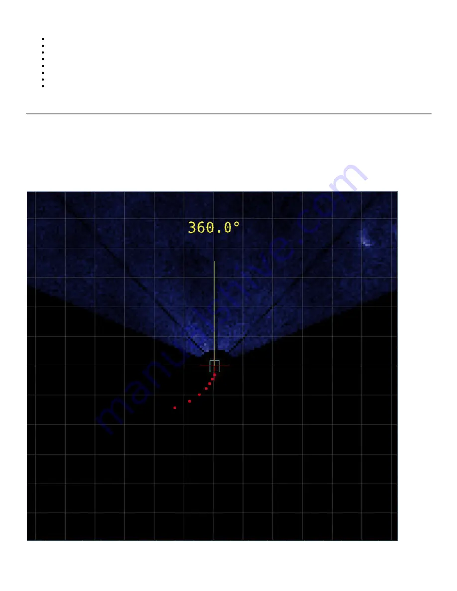
The navigation chart display is the main panel in the pilot interface. It allows the user to monitor the position of the ROV in real­time. It

is also possible to use the navigation chart display to generate pilot commands for the ROV by selecting coordinate locations with a

mouse when in an Auto Fly mode. For example, when in AUTO FLY Click and Go mode, a left­button mouse click in this display

generates a new position request for the ROV, and a right­button mouse click generates a new heading request. The background of

the Navigation Chart Display can be either a grid or a chart. A sonar image overlay can also be displayed for target recognition and

location determination.

The navigation chart displays a plan view of the ROV and the surrounding area. The ROV position is calculated by VideoRay RI

CoPilot's navigation system ­ the accuracy of which depends on the frequency and quality of the absolute navigation fixes. The

display is always centered on the ROV, so it will appear as if the grid or chart is moving under the ROV.
By default, magnetic north is up on the screen. The ROV will rotate in the center of the screen to reflect the current ROV heading.

Содержание SeeByte Reacquire and Identify CoPilot

Страница 1: ......

Страница 2: ...Notice This material is copyright protected No material may be reproduced or transmitted in any form or by any means for any purpose without expressed written consent of VideoRay LLC Copyright 2016 V...

Страница 3: ...Sonar DVL GPS Software Guide Navigation Chart Display Water Column Display Flight Status Panel Flight Controls Panel MANUAL Mode Stay Command Velocity Controls AUTO HOVER Mode AUTO FLY Mode Click and...

Страница 4: ...e icon is used to highlight a specific detail or point of information The Tip icon is used to highlight a suggestion or recommendation Beyond this Document There is no substitute for experience and or...

Страница 5: ...associated products and services are subject to change without notice Online Manual The full version of this manual is available online in the following formats http download videoray com documentatio...

Страница 6: ...ne 1 610 458 3000 select option 1 Skype videoray support by appointment Remote Sessions www videoray com support remote support html by appointment Regional Support VideoRay Authorized Service Centers...

Страница 7: ...location A DP system mimics automatically what a pilot would do in adjusting the thrusters to keep the desired position The pilot can easily control the ROV using the DP system For example if the pil...

Страница 8: ...e in contact with water or allow power cord connectors or the control panel to enter the water The only components that can safely be placed in water are the submersible any onboard accessories and te...

Страница 9: ...s shown may be optional and not included with your configuration Pre Dive Preparations Select a safe and preferably level area to set up the control panel See the On site Operations section of the Pro...

Страница 10: ...f the tether to the control panel When not in use keep the tether connectors clean and protected for the best performance and reliability 5 Plug the control panel power cord into a conventional power...

Страница 11: ...the thrusters For the next two steps do not operate horizontal thrusters out of water for more than 30 seconds to avoid overheating or premature wear of the cartridge seals 1 Gently move the joystick...

Страница 12: ...oo high you will need to add some ballast weights If the ROV sinks you will need to remove some ballast weights If the ROV is not floating level you can change the locations of the weights The buoyanc...

Страница 13: ...half hour After cleaning the ROV and tether they should be allowed to air dry before being put away for storage Failure to properly maintain the ROV by thoroughly cleaning it after use may dramatical...

Страница 14: ...ot RI Operator s Manual 2 00 00 Requirements Specifications CoPilot RI features and specifications are subject to change without notice Product News See www videoray com for the most up to date produc...

Страница 15: ...get Nudge Box A tolerance indicator on the screen that represents the area of proximity around the ROV If the objective location is within this nudge box the ROV is considered in position Objective Lo...

Страница 16: ...ual Sonar Forward looking imaging sonar provides extended visual range capabilities Possible targets of interest can be observed and marked and the system can navigate to them manually or automaticall...

Страница 17: ...eoRay Cockpit control bar This will start a Virtual Machine which will appear on the second monitor by default On the desktop of the virtual machine there is a program icon for the CoPilot RI program...

Страница 18: ...mple when in AUTO FLY Click and Go mode a left button mouse click in this display generates a new position request for the ROV and a right button mouse click generates a new heading request The backgr...

Страница 19: ...Dots Markers Yellow Dot Selected marker Navigation Chart Display Zoom Scale Control The navigation chart display zoom scale allows the user to change the viewable area and displayed size of objects T...

Страница 20: ...Flight Status Panel The Flight Status Panel is displayed in the upper left of the interface It provides real time information about the position and movement of the ROV...

Страница 21: ...d No values are displayed if no ROV information is detected Flight Controls Panel The Flight Controls Panel is used to select the flight mode and indicate which flight mode is active It is also used t...

Страница 22: ...eferences setting for Enable Station Keeping The Stay command can be used to stop the ROV in an emergency while it is in an auto flight mode Velocity Controls The velocity controls allow the user to s...

Страница 23: ...sired location or series of locations specified by the user There are several Auto Fly modes After selecting Auto Fly the user selects the Auto Fly sub mode 1 Click and Go 2 Go to Waypoint a Global Wa...

Страница 24: ...location will become to location of the ROV when the pilot releases the joystick To stop the ROV while under CoPilot control press the Stay command button Pressing the Stay command will cause the syst...

Страница 25: ...not use the joystick to override Auto Fly Go to Waypoint mode for horizontal or vertical control of the ROV To stop the ROV while under CoPilot control press the Stay command button Pressing the Stay...

Страница 26: ...OV s maximum speed is still restricted by the speed selection If you want full power you will need to change to Manual mode If the system loses DP while in an Auto Fly mode Auto Fly mode will be cance...

Страница 27: ...user will then be instructed to enter the coordinates of their chosen location into the window Once entered the user should click save to place the marker If incorrect coordinates have been entered a...

Страница 28: ...Editing Markers To change the location of a specific marker there are two possible actions that can be undertaken 1 Using the Pilot Interface Select the Marker you wish to edit by right clicking on th...

Страница 29: ...ing Yellow Nav Local The navigation reference frame is in local coordinates and based on DVL tracking Red Nav Fault The navigation system is unable to track the position of the ROV In Position Gray In...

Страница 30: ...t above the waterfall of the interface toolbar These additional functions include Toggle GPS On or Off Toggle GPS On or Off Set Location Set Location Start Stop Recording Start Stop Recording Take a S...

Страница 31: ...hot Snapshot Chart Controls Load Chart View Controls Erase Breadcrumb Trail Set Grid Orientation Grid Settings Sonar Controls Sonar Toggle Auto Intensity Toggle Color Map Selection Threshold Intensity...

Страница 32: ...deoRay Cockpit Cockpit operates in override mode This allows CoPilot RI to send piloting commands to the ROV through Cockpit If the system becomes unstable while in an auto flight mode the Override ca...

Страница 33: ...rrect True North reading of 0 when the ROV is pointed True North The declination is saved from session to session Be sure to clear it or change it at the start of each session if necessary Beginning w...

Страница 34: ...ector Nav compass follow these steps 1 Start VideoRay Cockpit 2 Click on the Engine Room button on the Control Bar 3 Unlock the controls 4 Click on the Calibrate Compass button which has the magnet ic...

Страница 35: ...ees Lower the ROV to face straight down again Rotate 15 degrees and repeat this process of up and down arcs until you have rotated a full circle 14 Continue until the measurements have been completed...

Страница 36: ...he number of satellites being observed is indicated by blue indicator lights Filters Filters allow for better operational performance by eliminating GPS fixes that are based on poor data and have a gr...

Страница 37: ...is is standard on VideoRay provisioned production machines This setup also requires systems using a ROV GPS Mast and DVL to have the device PAMS programmed with the standard ID s This may NOT be the c...

Страница 38: ...chine be connected to the internet 15 Make sure the SeeByte HASP USB license key is inserted into a USB port 16 In the blue Virtual Machine menu bar at the top of the screen select Virtual Machine Rem...

Страница 39: ...CoPilot RI runs in a virtual machine Therefore it does not have access to all folders on the host computer It only has access to those folders that are shared which includes the folders listed above...

Отзывы: