125
124
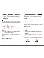
The polarity lead is used to connect the MIG Gun to the appropriate positive or negative output
terminal (allowing polarity reversal for different welding applications). In general, the polarity
lead should be connected in to the positive welding terminal (+) when using steel, stainless
steel or aluminum electrode wire. When using gasless wire, the polarity lead is generally connected
to the negative welding terminal (-). If in doubt, consult the manufacturer of the electrode wire
for the correct polarity. It is essential, however, that the male plug is inserted and turned securely
to achieve a sound electrical connection.
2.3 MIG Gun Polarity Lead
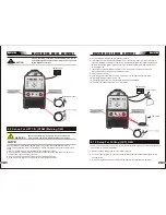
15. Remote Control Switch
Remote Control Switch
receptacle is used to connect a trigger switch or remote
control to the welding Power Source circuitry:
To make connections, align keyway, insert plug, and rotate threaded collar fully clockwise.
The socket information is included in the event the supplied cable is not suitable and it
is necessary to wire a plug or cable to interface with the receptacle.
16. Shielding Gas Outlet
The Shielding Gas Outlet located on the front panel is a fast connection of a suitable
TIG Torch.
Operation
MIG
SERIES
EQUIPMENT
MIG SERIES
EQUIPMENT
5. Digital Voltmeter
The digital meter is used to display the pre-set (preview) Voltage in Mig modes and
actual welding Voltage of the power source when welding. This digital meter is used to
display the Welding Output Terminal Voltage in STICK modes during non- welding or
welding.
7. Positive Control
The positive control is used to plus selected function from 6.
8. Negative Control
The negative control is used to minus selected function from 6.
11. 0.6/0.8/1.0/SPL
Press this button to choose the welding materials diameter, SPL is stainless steel.
14. Positive Welding Output Terminal
The positive welding terminal is used to connect the welding output of the power source
to the appropriate welding accessory such as the MIG Gun (via the MIG Gun polarity
lead) or ground clamp (for Stick function). Positive welding current flows from the
power source via this heavy duty bayonet type terminal. It is essential, however, that the
male plug is inserted and turned securely to achieve a sound electrical connection
.
6. Selecting function Button
Press and release this button to change the selected weld functions mode from welding
current to inductance to Volt to Burnback .
10. 2T - 4T Trigger Latch Button
Press and release the button to change the selected operating mode of the trigger. The
selected mode can be either “2T” (unlatched) or “4T” (latched) operation. The green
indicator next to the button will illuminate to identify which mode is selected (2T or 4T).
In the 4T mode once the weld has been started you can release the trigger and
continue welding until the trigger is activated again or the welding arc is broken to stop
the welding arc.
12. MIG Torch Connecting
The MIG Torch Adapter is the connection point for the MIG Torch. Press the MIG Torch
in and secure by turning the locking ring to the right (clockwise)
13. Negative Welding Output Terminal
The negative welding terminal is used to connect the welding output of the power source
to the appropriate welding accessory such as the earth clamp (for Mig function) or
electrode holder (for Stick function). Negative welding current shows to the power
source via this heavy duty bayonet type terminal. It is essential, however, that the male
plug is inserted and turned securely to achieve a sound electrical connection.
9. Weld Process Selection Button
Press and release this button to change the selected weld process mode from mig to
tig to stick. The weld process will change to the next process in the sequence each time
the button is pressed and released. The green indicators next to the button will
illuminate to identify mig to tig to stick process mode.
Operation


