Hardware Installation
NetCam1S, NetCam6, NetCamPlus Manual, © VCS GmbH
21
3.3.3
Video Output
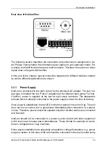
Connection is provided at the RCA socket labeled ‘Monitor’ for NetCam1E receiver or
NetCam6. For NetCamPlus, a BNC socket is provided which is labelled ’Video’. Net-
Cam is compatible with any black and white or color monitor, capable of displaying
(F)BAS signals of the corresponding television standards PAL/CCIR or NTSC/
RS170. The video output is to be terminated with 75
Ω
.
If a BNC plug is to be connected, an appropriate adapter from RCA to BNC from the
adapter set (not supplied) is to be used.
For a NetCam6 sending unit or NetCamPlus, the main purpose of the video output is
to display the live video picture which is sent to the receiver via ISDN. Additionally,
the local video output may prove useful during installation in order to check correct
aim and alignment of camera mounting and lens focus and zoom settings. The video
output signal for NetCamPlus is the analog output of the internal camera module. The
signal is always available, independent from the status of the line connection. For
NetCam6, a connected PC running the NCTerm terminal program can be used to
switch locally between the six video inputs. In addition, NetCam6 may also be used
as a hardware receiver.
F
Note:
The monitor connected to the video output of a NetCam1E hardware
receiver is the operator’s monitor. It displays the video pictures re-
ceived from the sending unit. The recommended screen size is de-
pendent on the distance between user and monitor. Usually viewing
distance is between 4 and 5 times the screen size (diagonal).
3.3.4
Alarm Inputs
NetCam1 and NetCamPlus are equipped with one alarm input each, while NetCam6
has seven alarm inputs total. External alarm sensors can be connected to these in-
puts. External alarm sensors, e.g. infrared motion detectors, may trigger the NetCam
system, which will subsequently dial a preconfigured alarm telephone number and es-
tablish a connection with a receiver, e.g. an alarm monitoring center.
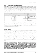
The following figures show the relevant terminals for connection of external sensors
like contacts, breaking glass sensors or motion detectors, for example. Installation is
through the socket labelled ’Alarm’, pins ’Input+’ and ’Input-’, or at the screw terminals
labelled ’IN’.
Содержание NetCam1
Страница 1: ...NetCam1 NetCam6 NetCamPlus Manual VCS Video Communication Systems GmbH...
Страница 6: ...NetCam1S NetCam6 NetCamPlus Manual VCS GmbH 6...
Страница 42: ...NetCam1S NetCam6 NetCamPlus Handbuch VCS GmbH 42...
Страница 80: ...Configuration Using NCTerm NetCam1S NetCam6 NetCamPlus Manual VCS GmbH 80...
Страница 90: ...Appendix NetCam1S NetCam6 NetCamPlus Manual VCS GmbH 90...

