WRM-10P AND WRM-40 USER’S MANUAL
REV 3
2
1.0 INTRODUCTION
1.1
General Description and Features
The WRM-10P is designed to accurately measure the winding resistance of highly inductive
power transformers. The unit’s dual resistance-reading input channels can measure two
winding resistances simultaneously, and four-wire (Kelvin) connections provide high accuracy
and require no lead compensation. The WRM-10P provides stable resistance readings of very
large transformers by utilizing a 36 Vdc power supply capable of outputting up to 10 Amperes.
The resistance reading of a 100MVA transformer can be achieved in 5 minutes or less. The
unit’s power supply is cooled by heavy-duty fans designed for continuous operation. For greater
flexibility in the field, the WRM-10P comes with a built-in 2.5-inch wide thermal printer used for
printing test reports.
Since the WRM-10P can accurately measure resistances ranging from 1 micro-ohm to 2,000
ohms, it can also be used to measure EHV circuit-breaker contact resistance, motor winding
resistance, or any low resistance. If the transformer winding temperature is entered, the WRM-
10P can calculate the equivalent resistance value of the winding material (aluminum or copper)
at any standard reference temperature. Also, a special test mode can run a test for up to 45
minutes while saving resistance readings at one-minute intervals. In addition to measuring the
resistance value, the WRM-10P also checks the “make-before-break” tap-switching sequences
of voltage regulators and load tap changers.
The WRM-10P can store test results in Flash EEPROM. Test results can be printed on the built-in
2.5-inch wide thermal printer or can be transferred to a PC via the RS-232C interface port.
The WRM-40 has all the features of the WRM-10P, but is capable of outputting up to 40
Amperes. The WRM-10P has a resistance reading range of 1 micro-ohm to 2,000 ohms while
the WRM-40 has a resistance reading range of 1 micro-ohm to 500 ohms.
The WRM-10P and WRM-40 come furnished with three 50-foot test cables. Each test cable lead
is terminated with a quick-disconnect test clip.
Built-in Safety Features
At the end of each test, the WRM automatically dissipates the stored energy in the transformer.
This discharge circuit will continue to work even if the supply voltage is lost. For added safety,
the unit’s power supply is thermally protected from over-load damage.
User Interface
The WRM features a back-lit LCD screen (20 characters by 4 lines) that is viewable in both bright
sunlight and low-light levels. A rugged, alpha-numeric, membrane keypad is used to control the
unit.
Содержание WRM-10P
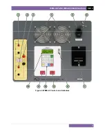
Страница 12: ...WRM 10P AND WRM 40 USER S MANUAL REV 3 8 Figure 2 WRM 40 Controls and Indicators...
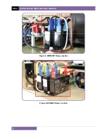
Страница 15: ...REV 3 WRM 10P AND WRM 40 USER S MANUAL 11 Figure 5 WRM 10P Relay Location Figure 6 WRM 40 Relay Location...
Страница 39: ...REV 3 WRM 10P AND WRM 40 USER S MANUAL 35 Figure 14 Typical LTC Voltage Regulator Test Report Printout...
Страница 44: ...WRM 10P AND WRM 40 USER S MANUAL REV 3 40 Figure 15 Typical Five Minute Special Test Report Printout...
Страница 54: ...WRM 10P AND WRM 40 USER S MANUAL REV 3 50 Figure 17 Typical Test Record Directory Printout...


