


WRM-10P AND WRM-40 USER’S MANUAL
REV 3
14
3.0 OPERATING
PROCEDURES
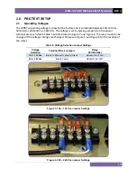
3.1
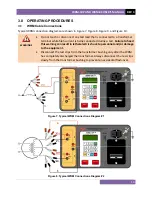
WRM Cable Connections
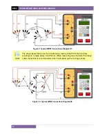
Typical WRM connection diagrams are shown in Figure 7, Figure 8, Figure 9, and Figure 10.
WARNINGS
•
Do not touch or disconnect any test lead that is connected to a transformer
terminal while high current is being conducted during a test.
Failure to heed
this warning can result in lethal electric shock to personnel and/or damage
to the equipment.
•
Disconnect the test clips from the transformer bushing only after the WRM
has completely discharged the transformer. Always disconnect the test clips
slowly from the transformer bushing to prevent an accidental flash-over.
Figure 7. Typical WRM Connections Diagram #1
Figure 8. Typical WRM Connections Diagram #2
Содержание WRM-10P
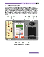
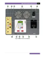
Страница 12: ...WRM 10P AND WRM 40 USER S MANUAL REV 3 8 Figure 2 WRM 40 Controls and Indicators...
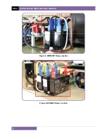
Страница 15: ...REV 3 WRM 10P AND WRM 40 USER S MANUAL 11 Figure 5 WRM 10P Relay Location Figure 6 WRM 40 Relay Location...
Страница 39: ...REV 3 WRM 10P AND WRM 40 USER S MANUAL 35 Figure 14 Typical LTC Voltage Regulator Test Report Printout...
Страница 44: ...WRM 10P AND WRM 40 USER S MANUAL REV 3 40 Figure 15 Typical Five Minute Special Test Report Printout...
Страница 54: ...WRM 10P AND WRM 40 USER S MANUAL REV 3 50 Figure 17 Typical Test Record Directory Printout...


