WRM-10P AND WRM-40 USER’S MANUAL
REV 3
44
3.8
Performing a Diagnostic Test
In diagnostic mode, the WRM can run a resistance test, display the sense voltages, and test
current on the WRM. This feature can be used to verify the WRM’s voltage and current
readings against an external meter. Use the steps below to perform a diagnostic test:
a.
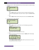
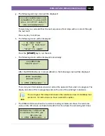
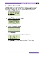
Start from the “START-UP” menu:
Press the
[3]
key (
USER DIAG
).
b.
The following warning screen will be displayed:
Press any key to continue.
c.
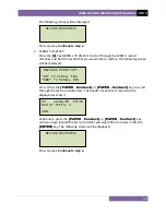
The following screen will be displayed:
Press the
[START]
key.
d.
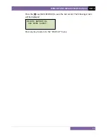
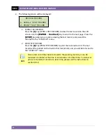
The V1, V2, and test current (I) will be displayed as shown below:
Press the
[STOP]
key to end the test and return to the “START-UP” menu.
V1 = 28.13 mV
V2 = 09.23 mV
I = 1.091 A
* XFMR ENERGIZED! *
- USER DIAG TEST –
“START” TO RUN TEST
OR
“STOP” TO ABORT
********WARNING******
DANGEROUS FLASH-OVER
WILL OCCUR IF CABLES
ARE DISCONNECTED!
1.
TEST XFMR 11/02/09
2.
SETUP 12:33:01
3.
USER DIAG
Содержание WRM-10P
Страница 12: ...WRM 10P AND WRM 40 USER S MANUAL REV 3 8 Figure 2 WRM 40 Controls and Indicators...
Страница 15: ...REV 3 WRM 10P AND WRM 40 USER S MANUAL 11 Figure 5 WRM 10P Relay Location Figure 6 WRM 40 Relay Location...
Страница 39: ...REV 3 WRM 10P AND WRM 40 USER S MANUAL 35 Figure 14 Typical LTC Voltage Regulator Test Report Printout...
Страница 44: ...WRM 10P AND WRM 40 USER S MANUAL REV 3 40 Figure 15 Typical Five Minute Special Test Report Printout...
Страница 54: ...WRM 10P AND WRM 40 USER S MANUAL REV 3 50 Figure 17 Typical Test Record Directory Printout...


