REV 3
WRM-10P AND WRM-40 USER’S MANUAL
53
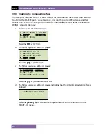
3.10 Enabling the Computer Interface
The Computer Interface Mode is used to transfer test records from the WRM’s Flash EEPROM
to a PV via the RS-232C port. To use this mode, first run the provided PC software and then
connect the PC to the RS-232C port on the WRM. Then follow the steps below to enable the
WRM’s computer interface:
a.
Start from the “START-UP” menu:
Press the
[2]
key (
SETUP
).
b.
The following screen will be displayed:
Press the
[4]
key (
NEXT PAGE
).
c.
The following screen will be displayed:
Press the
[1]
key (
COMPUTER CONTROL
).
d.
The following screen will be displayed, indicating that the WRM’s computer interface is
enabled:
Press the
[STOP]
key to disable the computer interface mode and return to the
“START-UP” menu.
COMPUTER ITF MODE
1.
COMPUTER CONTROL
2.
SET TIME
3.
VOLTAGE REG. TEST
1.
ENTER XFMR ID
2.
REVIEW RECORD
3.
RESTORE RECORD
4.
NEXT PAGE
1.
TEST XFMR 11/02/09
2.
SETUP 12:33:01
3.
USER DIAG
Содержание WRM-10P
Страница 12: ...WRM 10P AND WRM 40 USER S MANUAL REV 3 8 Figure 2 WRM 40 Controls and Indicators...
Страница 15: ...REV 3 WRM 10P AND WRM 40 USER S MANUAL 11 Figure 5 WRM 10P Relay Location Figure 6 WRM 40 Relay Location...
Страница 39: ...REV 3 WRM 10P AND WRM 40 USER S MANUAL 35 Figure 14 Typical LTC Voltage Regulator Test Report Printout...
Страница 44: ...WRM 10P AND WRM 40 USER S MANUAL REV 3 40 Figure 15 Typical Five Minute Special Test Report Printout...
Страница 54: ...WRM 10P AND WRM 40 USER S MANUAL REV 3 50 Figure 17 Typical Test Record Directory Printout...

