REV 3
WRM-10P AND WRM-40 USER’S MANUAL
15
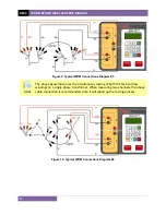
Figure 9. Typical WRM Connections Diagram #3
NOTE
The above figure illustrates the simultaneous testing of both the high and low
windings on a single-phase transformer. When measuring two channels, the above
cable connection is recommended since it will speed up the testing process.
Figure 10. Typical WRM Connections Diagram #4
Содержание WRM-10P
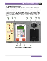
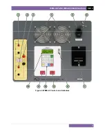
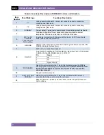
Страница 12: ...WRM 10P AND WRM 40 USER S MANUAL REV 3 8 Figure 2 WRM 40 Controls and Indicators...
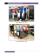
Страница 15: ...REV 3 WRM 10P AND WRM 40 USER S MANUAL 11 Figure 5 WRM 10P Relay Location Figure 6 WRM 40 Relay Location...
Страница 39: ...REV 3 WRM 10P AND WRM 40 USER S MANUAL 35 Figure 14 Typical LTC Voltage Regulator Test Report Printout...
Страница 44: ...WRM 10P AND WRM 40 USER S MANUAL REV 3 40 Figure 15 Typical Five Minute Special Test Report Printout...
Страница 54: ...WRM 10P AND WRM 40 USER S MANUAL REV 3 50 Figure 17 Typical Test Record Directory Printout...


