


WRM-10P AND WRM-40 USER’S MANUAL
REV 3
38
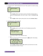
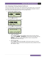
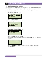
g.
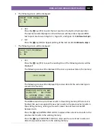
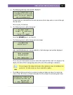
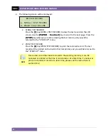
The following warning screen will be displayed:
This warning is a reminder that the next sequence of test steps will run current through
the test load.
Press any key to continue.
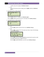
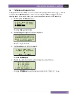
h.
The following screen will be displayed:
Press the
[START]
key to run the test.
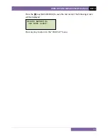
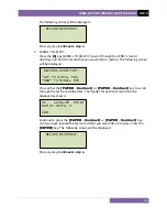
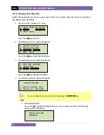
i.
The following screen will be displayed momentarily:
After the WRM finishes its internal calibration, the following screen will be displayed:
This is only an informational screen to remind the operator that a test is in progress. The
display duration of this message depends on the size of the winding’s inductance.
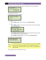
NOTE
You can bypass this delay and observe the resistance value immediately. See
section 4.1 for instructions on how to select this option.
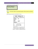
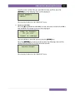
j.
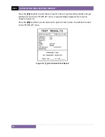
The WRM determines when the resistance reading is stable and shows the resistance
value on the LCD screen as shown below (the first line shows the remaining test time):
REMAINING TIME=10:00
I=10.01A R1=499
μΩ
R2=501
μΩ
* XFMR ENERGIZED! *
XFMR CHARGING
PLEASE WAIT…
* XFMR ENERGIZED! *
CALIBRATING
PLEASE WAIT...
- V1 ONLY TEST –
“START” TO RUN TEST
OR
“STOP” TO ABORT
********WARNING******
DANGEROUS FLASH-OVER
WILL OCCUR IF CABLES
ARE DISCONNECTED!
Содержание WRM-10P
Страница 12: ...WRM 10P AND WRM 40 USER S MANUAL REV 3 8 Figure 2 WRM 40 Controls and Indicators...
Страница 15: ...REV 3 WRM 10P AND WRM 40 USER S MANUAL 11 Figure 5 WRM 10P Relay Location Figure 6 WRM 40 Relay Location...
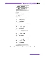
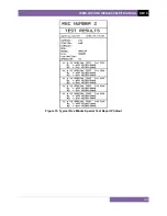
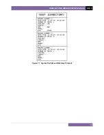
Страница 39: ...REV 3 WRM 10P AND WRM 40 USER S MANUAL 35 Figure 14 Typical LTC Voltage Regulator Test Report Printout...
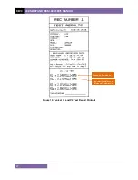
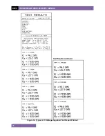
Страница 44: ...WRM 10P AND WRM 40 USER S MANUAL REV 3 40 Figure 15 Typical Five Minute Special Test Report Printout...
Страница 54: ...WRM 10P AND WRM 40 USER S MANUAL REV 3 50 Figure 17 Typical Test Record Directory Printout...


