56
D
Installing the APP receiver to the Control Board
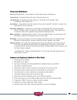
The USAutomatic NEXXGATE receiver module
connects to the J7 plug on the control board.
Follow the instructions included with the
NEXXGATE receiver for setup.
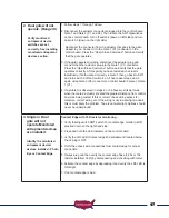
For solar chrged systems a 20 watt panel
is recommended part #520030
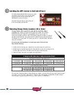
Extending Charge Device Location (AC or Solar)
If charge device cable needs to be extended to reach the charge
controller
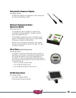
use “Ranger Charge Cable Extension Pigtails” Part Number
630038 (see figure). These DC plug pigtails connect to each end of a
customer provided extension cable. Connections should be made in customer
provided water tight box. Use charts below to determine wire size needed for
the distance to be extended. The cable must be a 2 conductor cable, stranded
wire recommended.
Do not modify the transformer or solar panel cable, this will void
the product warranty.
1. Splice mate for the charge controller to cable end located in control box.
2. Splice mate for the charge device to cable end that connects to charge device.
A water tight junction box should be used to keep connections dry.
3. Install DC plug connection and splice into junction box.
Charge Cable Extension Cable Selection Chart
Transformer Extension Wire Size Chart
0 to 100 ft
101 to 250 ft
251 to 500 ft
501 to 750 ft
750 to 1000 ft
18 gauge wire
16 gauge wire
14 gauge wire
12 gauge wire
10 gauge wire
Solar Extension Wire Size Chart
15 to 100 feet
100 to 250 feet
250 to 500 feet
18 gauge wire
16 gauge wire
14 gauge wire
The wire used must be rated for Direct Burial use, unless in conduit. Wire ran in conduit must be rated
for outdoor use. The above Table lists the recommended wire gauge per application length. Using a
smaller gauge may impede performance or cause system to malfunction
C

