background image

24

12

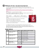
Installing Monitored Entrapment Protection Devices

When the installation requires more than 1 monitored contact edge or 2 monitored photo eyes, the 

Monitored Entrapment Device Expansion Modual must be installed. (USAutomatic Part# 500015)

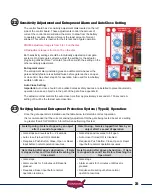
Monitored Photo Eye (Type B1) Installation


for Entrapment Protection ONLY. 

(page 3)

  Connect wires per the table below: All wiring should be done with power disconnected from control board.

Photo Eye wiring for Entrapment Device Protection

Photo Eye Connections

Ranger Control Board Connections

Power +12 vdc

J2 pin 12

Power ground / O

J2 pin2, pin 5 or pin 7

Common

J2 pin2, pin 5 or pin 7

N/C contact Closed Direction

J2 pin 8

N/C contact Open Direction

J2 pin 4

The energy saving design of the control board will only apply 12 vdc to the photo eye when the gate is in 

operation. During instal12 vdc power is required to align the photo eye beam. 
Set control board SW1 dipswitches as follows for the installation:

Control Board Dipswitch Settings for Installation

SW1 switch 3

OFF – press down on the left hand side

SW1 switch 4

OFF – press down on the left hand side

SW1 switch 10

ON – press down on the right hand side

Install the photo eye at this time. Once power is applied to the system, verify alignment. Step 18.

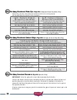
Monitored Contact Edge (Type B2) Installation 

for Entrapment Protection ONLY.

Connect wires per the table below: All wiring should be done with power disconnected from  

control board. Contact edge must have 8.25K or 10K ohm resistor built into device.

Contact Edge wiring for Entrapment Device Protection

Contact Edge Connectons

Ranger Control Board Connections

N/O connection

J2 pin 6

Common

J2 pin 2, pin 5 or pin 7

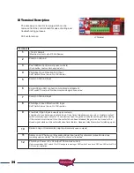
Constant Pressure (Type D) Installation

Connect wires per the table below: All wiring should be done with power disconnected from  

control board. The included warning placard must be installed by the control switch

Type D wiring for Emergency / Constant pressure Operation

Constant Pressure Switch N/O type

Ranger Control Board Connections

N/O connection

J5 pin 1

Common

J5 pin 2

12

b

12

c

12

a

Содержание Ranger HD

Страница 1: ... Powered Solar or AC Charged Ranger Swing Gate Operators 16 Inch Stroke Ranger HD Swing Gate Operator 24 Inch Stroke Installation Owners Manual www USAutomaticGateOpeners com 800 878 7829 Sales USAutomaticGateOpeners com ...

Страница 2: ...olar Friendly meaning that they require the least amount of energy possible to perform the job they were designed to do The solar option allows you to install the gate operator in remote areas or in applications where you prefer to be solar charged Solar charging provides additional isolation from lightning that might damage the unit via the AC power needed for the transformer BATTERY REQUIRED FOR...

Страница 3: ...er Control Box and Linear Actuator Cable 22 11 Splicing Linear Actuator Cable Cable and Dual Gate Cable 23 12 Installing Monitored Entrapment Protection Devices 24 Monitored Photo Eye Installation 24 Monitored Contact Edge Installation 24 Constant Pressure Installation 25 13 Install Wiring Harness and Battery 24 14 Install Battery Controller Power Source AC or Solar 25 26 15 Connect Power Source t...

Страница 4: ...he USAutomatic expansion module part 500015 is required Type B1 Non contact sensor photoelectric sensor or the equivalent Identified as Normally Closed N C contact switching Type B2 Contact sensor edge device or the equivalent Identified as 10K resistor installed for presence monitoring Type D Actuating device requiring continuous pressure to maintain motion of the gate User must be within sight o...

Страница 5: ...h less than 16 inches 40 6 cm of clearance recommended monitored entrapment protection type B1 photo eye or equivalent If space is less than 16 40 6 cm entrapment protection in this area is required ASTM F2200 7 1 1 1 and 7 1 1 2 Zone C If distance from center of hinge rotation point to corner of column post or immovable object is greater than 4 inches 10 16 cm recommended monitored entrapment pro...

Страница 6: ...trians must be supplied with a separate access opening The pedestrian access opening shall be designed to promote pedestrian usage Locate the gate such that persons will not come in contact with the vehicular gate during the entire path of travel 11 The gate must be installed in a location so that enough clearance is supplied between the gate and adjacent structures when opening and closing to red...

Страница 7: ...ch as the area reachable by a moving gate Contact Sensors Type B2 Contact Edge or equivalent 1 See entrapment zones for suggestions on placement of sensors 2 One or more sensors shall be located on the inside and outside leading edge of a swing gate 3 Additionally if the bottom edge of a swing gate is greater than 4 inches 101 6mm and less than 16 inches 406mm above ground at any point in its arc ...

Страница 8: ...30020 HD 40 Part 630036 PRO80 35 Ranger II ONLY 2 Button Transmitter Part 030210 2 per DC Adapter 20vdc and 1 2 Amps Part 520009 with AC Models Solar Panel Kit Part 520026 with Solar Models 10w Safety Signs Part 601020 2 per Photo Eyes Part 550011 1 set per Optional Accessories LCR Items See accessories section for complete list and descriptions 4 Button Transmitter Part 030212 Push to Operate But...

Страница 9: ...16 Ranger I 2 per Ranger II 4 per Lock Nuts Part 610518 Ranger I 1 per Ranger II 2 per Threaded Cable Strain Relief Conn Part 630022 1 per 12 Self Tapping Hex Screw Part 610532 4 per HARDWARE INVENTORY SAE Standard wrenches sockets Welder Nut driver Drill and bits Level and tape measure Drill adapter for socket attachment Pliers Hack saw Wire Cutters Strippers Welding is the recommended method of ...

Страница 10: ...ear box to front Rear housing to motor end TOP VIEW TOP VIEW Housing width 3 Housing width 3 2 42 5 25 25 30 25 17 25 7 75 5 25 9 7 25 3 25 75 Measurements are to center of hole Measurements are to center of hole Ranger HD Pro 80 ...

Страница 11: ...ht 400 lbs HD 18 feet length Max weight 800 lbs Ranch Gate PRO80 16 feet length Max weight 300 lbs HD 16 feet length Max weight 800 lbs Farm Gate PRO80 HD 20 feet max length Max weight 250 lbs Chain Link Gate PRO80 14 feet length Max weight 350 lbs HD 16 feet length Max weight 800 lbs BOX DIMENSIONS GATE QUALIFICATIONS APPLICATIONS Mounting Holes 4 Places 14 25 17 7 11 7 14 5 ...

Страница 12: ...roblems A wheel is generally a sign of a weak hinge system or a weak gate frame Is the gate frame of substantial strength without excessive weight Will the frame withstand normal wind load conditions without sway or vibration Will the gate close correctly without being hand guided or lifted to close Are the hinges suited for an automatic gate operator We recommend bearing type hinges to reduce fri...

Страница 13: ...30038 See Power Source Cable Extension chart for identifying the wire size needed for the distance required Transformer must be installed indoors or in a raintight enclosure Transformer should not be exposed to moisture 7 For Solar Charged System Where will the solar panel mount so that optimum sunlight is received Solar panel is provided with 15 feet of cable If extension is needed use power sour...

Страница 14: ...gate swings into the property and the operator pulls the gate open Push to Open Installation This installation method is commonly used where the drive slopes upward into the property and the operator pushes the gate open The gate swings outward away from the property 2 RETRACTED Gate Open RETRACTED Gate Closed EXTENDED Gate Closed EXTENDED Gate Open ...

Страница 15: ...o determine the location of the actuator mounting tube The actuator delivers force on the gate when operating Aligning the actuator mounts with a horizontal gate frame member is the best choice as shown here Installation of a horizontal brace may be necessary to prevent damage to vertical gate pickets Avoid mounting actuator on bottom rail of gate Unit will be more likely to be damaged by flooding...

Страница 16: ...und Post Wood or Aluminum Post Drill through mounted Drill through post and bracket Use carriage bolts with back plate not included 4a Actuator support bracket mounted horizontally on hinge post Actuator support bracket mounted vertically on hinge post Actuator support bracket mounted vertically on hinge post Actuator support bracket mounted vertically opposite hinge 3D Example On wood post Actuat...

Страница 17: ...mples below are for left hand installations Reverse for right hand installations Square Post Round Post Wood or Aluminum Post 4b Drill through mounted Drill through post and bracket Use carriage bolts with back plate not included Actuator support bracket mounted horizontally on hinge post Actuator support bracket mounted vertically on hinge post 3D Example ...

Страница 18: ...shown are for 90 95 opening New Construction Existing Columns Actuator Mounting Bracket Installation Dimensions Operator Dimension A Dimension B Ranger HD 13 6 Ranger Pro80 7 5 Set hinge post in corner Set hinge post behind column center of hinge center of hinge Dim A Dim A 4c Dim B Dim B ...

Страница 19: ...ounting location of the Actuator Support Bracket mount the support bracket in alignment with predetermined horizontal frame member as per the following examples Bracket must be level in all directions DO NOT mount support bracket in a manner that obstructs gate movement or creates a pinch point 5 ...

Страница 20: ... degree opening 9 10 8 5 120 degree opening 11 8 6a Dim A Dim A Dim B Dim B Dimensions shown are for 90 95 opening Install Actuator Mounting Tube PULL TO OPEN PRO80 or HD Cut Actuator Mount Tube to proper length Weld to support bracket See table below for desired dimensions The actuator mounting tube will need to be cut so that the hole location matches the dimensions for a pull to open system IMP...

Страница 21: ...rt below Before welding in place ensure the actuator mounting tube is level in all directions and pivot hole location on actuator mounting tube is at proper point per the dimension chart for the type of installation being performed Dim A Dim B C u t L i n e PUSH TO OPEN Actuator Hinge Mounting Tube Installation Dimensions Gate opening in degrees Ranger HD Dimension A Ranger HD Dimension B Ranger P...

Страница 22: ...lon Washer Part 610528 Nylon Washer Part 610528 Bronze Bushing Part 610530 Bronze Bushing Part 610530 Nylon Washer Part 610529 Nylon Washer Part 610529 Bronze Bushing Part 610530 Bolt Part 610512 SAE Flat Washer Part 610516 Mounting Tube Part 610420 SAE Flat Washer Part 610516 inch Lock Nut Part 610518 Bolt Part 610512 SAE Flat Washer Part 610516 Mounting Tube Part 610420 SAE Flat Washer Part 6105...

Страница 23: ...e bracket should be installed on the gate 3 Weld or bolt the gate bracket to the gate 4 Connect actuator to gate bracket at this time and install manual release pin PUSH TO OPEN INSTALLATION ONLY The linear actuator was shipped from the factory set to the fully retracted position The steps below will determine where the gate bracket is to be installed on the gate 1 Swing gate to the fully closed p...

Страница 24: ...l box in a location that will allow the cable to be neatly routed If it must be longer than the 8 feet see Splicing Actuator Cable Step Also avoid choosing a mounting location that is near sprinklers We have provided knockouts for conduit fittings in the control box bottom right corner We highly recommend using conduit for all accessory wiring entering the control box Determine which knockouts are...

Страница 25: ...10 can be custom ordered and purchased in any length Never make underground splices as moisture in connections will definitely cause system malfunctions 5 Route the linear actuator cable into the junction box through the bottom of the box and determine length Allow ample slack in the cable for actuator movement when opening and closing the gate Cut cable longer than needed for future servicing 6 R...

Страница 26: ...follows for the installation Control Board Dipswitch Settings for Installation SW1 switch 3 OFF press down on the left hand side SW1 switch 4 OFF press down on the left hand side SW1 switch 10 ON press down on the right hand side Install the photo eye at this time Once power is applied to the system verify alignment Step 18 Monitored Contact Edge Type B2 Installation for Entrapment Protection ONLY...

Страница 27: ...arged System The AC model gate operator comes with a low voltage transformer which plugs into the battery controller and can easily provide 575 cycles of operation a day without decreasing the battery charge In the event AC power goes out the operator will operate for weeks on the battery if cycles per day are below 20 before needing service Accessories connected to the operator are critical Alway...

Страница 28: ...est direction and be installed at the angle of the supplied solar panel bracket For proper operation the panel must have unobstructed sun Even a small amount of shade will cause the Solar Panel to cease charging Something as tiny as a fingertip shadow will affect the Solar Panel Solar panel may be moved up to 200 feet from the control box to achieve adequate sunlight See power source cable extensi...

Страница 29: ...ect red lead to positive and black lead to negative Verify that nothing is in the path of the gate If by chance it begins to move when power is applied be prepared to disconnect the actuator cable Ranger I Single Gate and Ranger II Dual Gates Locate the actuator cable and plug it into the Gate 1 actuator connector see image on the control board Only connect one actuator at this time Ranger II Dual...

Страница 30: ...switch 3 4 and 9 should be in the ON position SW1 switch 8 and 10 ON SW1 switch 7 and 10 ON SW1 switch 2 ON Dual PULL TO OPEN SW1 switch 3 4 should be in the ON position SW1 switch 8 and 10 ON SW1 switch 7 and 10 ON SW1 switch 2 ON Dual PUSH TO OPEN SW1 switch 3 4 9 should be in the ON position SW1 switch 8 and 10 ON SW1 switch 7 and 10 ON SW1 switch 2 ON 1 Locate the Open Close command button on ...

Страница 31: ... in desired position Avoid over extending 5 Limit adjustment is complete If a dual gate system continue with steps 8 14 below 6 Turn OFF the gate 1 or gate 2 dip switch that is not being used 7 Power cycle is required at this time Disconnect the quick connect plug from the actuator harness and then reconnect Dual Gate Limit Adjustment 8 Disconnect the gate 1 actuator from control board 9 Connect t...

Страница 32: ...were turned OFF the value would 0 max speed If switch 1 and 3 were turned ON the value would 5 If switch 2 and 3 were turned ON the value would 6 If switch 1 2 3 were turned ON the value would 7 slowest speed The higher the value the slower the speed Avoid setting the speed value to a very slow speed which would cause the motor to stall After speed value is changed cycle the gate multiple cycles t...

Страница 33: ... See appendix B The adjustment dial controls the auto close time from approximately 2 seconds to 150 seconds A setting of 0 will be the fastest auto close time Verifying Inherent Entrapment Protection System Type A Operation Once the gate operator is installed use the table below to determine correct operation It is recommended that the current sensitivity adjustment for the gate being tested be s...

Страница 34: ...tact Edge Activated 1st Time Gate stops and reverses for 2 seconds Gate stops and reverses to full open Auto close disabled Auto close if turned ON is still active Requires a Push Button Close or Open input before normal operation resumes If while opening after reversal above a 2nd sequential input is received gate must stop If while closing after reversal above a 2nd activation occurs before the ...

Страница 35: ...D push button requires constant pressure for gate operation The user must verify the gate path is clear before pressing the button to operate gate External Reset Connector Sensitivity Adjustments SW1 Dip Switches SW2 Dip Switches Gate 1 Limit Adjustments Gate 2 Limit Adjustments Timer to Close Delay Adjustment LCR Receiver Connector App Plug Type D Button System Reset Open Close Command J2 Termina...

Страница 36: ...Free Exit Open Input normally open contacts Loop input or any hold open input such as a 7 day timer telephone access unit or maintain contact switch normally open contacts These devices open the gate and will prevent the gate from closing if the contact is maintained Once the contacts have been released the gate can be closed with a closed signal device or the automatic close timer feature Receive...

Страница 37: ...to function OFF Gate 2 operator disabled 5 Electronic Gate Lock Solenoid Type ON Electric Gate Lock Enabled OFF Electric Gate Lock not activated 6 Magnetic Lock ON Mag lock Enable OFF Mag lock not active 7 Photo Eye Open Only N C Monitored Entrapment ON Monitor Photo Eye open direction only OFF No monitored Photo Eye open direction installed 8 Photo Eye Closed Only N C Monitored Entrapment ON Moni...

Страница 38: ... right transmitter button down Red light on transmitter should be on 3 Press the P2 push button until the green LD light comes on 4 Release both buttons Transmitter right button to receiver programming is complete Receiver Programming Relay P2 programming from momentary to latching mode to hold gate open See Receiver Programming on page 42 to complete Hold Gate Open programming Erasing Single Tran...

Страница 39: ...l to the receiver Valid access code was entered This is the Blue 5 key on the metal keypad NOTE Do not install keypad until Create Communication with Receiver P1 relay 1 has been completed Keypad Programming Create Access Code Code you use to operate the gate CAN NOT BE THE SAME AS THE MASTER PASSWORD 1 Enter the Master Password 11111 this is the factory default master password 2 Enter 9 If correc...

Страница 40: ...f 1 long beep is heard start over with step 1 3 Enter the Master Password up to 5 digits if less than 5 digits or B is required 4 Enter 8 5 Enter the Master Password again to verify 6 Press 8 If correct 2 short beeps New Master Password is set If 1 long beep is heard start over with step 1 Programming Master Password Back to Factory Default 11111 1 Enter 11111 2 Press 8 long beep 3 Enter PUK code ...

Страница 41: ... long beep is heard start over with step 1 3 Enter the Security Code created in the previous table If correct 2 short beeps after each switch number and switch position combination is entered 4 Enter or B 5 Enter 6 6 If correct 2 short beeps if 1 long beep is heard start over with step 1 Receiver Programming Hold Gate Open Relay P2 programming from momentary to latching mode to hold gate open 1 Pr...

Страница 42: ...hecked at least once a month for proper operation Periodic checking is also advised for the following 1 Battery terminals for corrosion clean as required 2 Hinges and pivot points need to be greased 3 Mounting bolts for correct tightness 4 Inspect weld points for cracks or other defects 5 Inspect wiring for cuts nicks or other defects 6 Inspect hinge post to ensure it is not moving or twisting 7 V...

Страница 43: ...magnetic lock delay circuit turn SW1 switch 6 on Connect the negative wire from the magnetic gate lock to negative post of the battery Connect the positive 12vdc wire from the magnetic gate lock to J8 Mag Lock terminal 1 For Dual Gates see Gate Delay Feature Section Exit Sensor Solar friendly device Preferred Technologies CP 3 3W Part Number 070305 The driveway exit sensor is a magnetic device tha...

Страница 44: ...to Operate 1 Install Battery 2 Place hand on face plate Unit should beep while hand is in place 3 While beeping press the P1 button on receiver for open and close operation 4 Hold P1 button about 2 seconds When gate moves programming is complete 2 Button LCR Transmitter Part Number 030210 Standard Transmitter for all USAutomatic operators Operating Frequency 433 92 MHz 4 Button LCR Transmitter Par...

Страница 45: ...ors up to 5 monitored contact edges 10K resistor and up to 4 monitored photo eyes N C contact NO 10K for a total of 9 devices 7 Day Timer Solar friendly device Part Number 550015 The optional 7 day timer can be used to open the gate at a preset time and if the auto close feature of the gate operator is being used the gate can then close automatically at a preset time The timer is supplied with 3 s...

Страница 46: ...ush button Type D protection This button makes it possible to operate the gate with the J2 Accessory plug removed Type D button will bypass all entrapment devices allowing gate operation Verify gate path is clear before pressing button Must hold button for gate operation 4 Low battery Audible notification If the battery voltage falls below 10 5 vdc the siren will beep 3 times rapidly pause 5 secon...

Страница 47: ...ard sensitivity circuit senses an obstruction it will reverse the gate and if a second obstruction is detected before the gate reaches a fully open or close limit the control board will shut down the operator and sound the entrapment alarm for five minutes or until the Reset button is pressed Low battery alarm if battery voltage falls below 10 5 vdc the siren will emit 3 quick burst and repeat eve...

Страница 48: ...ectly See installing monitored entrapment devices section 1 Open the control box cover locate the Open Close Command push button and press it to operate the gate 2 Press the Reset push button located above the Open Close Command button then push the Open Close command push button to operate the gate 3 Press and hold the LED Indicator push button and observe all of the red LED s a If any of the LED...

Страница 49: ... 3 again using Gate 2 X2 connector on control board in place of Gate 1 X1 4 If a problem is observed in steps 2 or 3 above most likely it was when the Gate 2 actuator located the greatest distance from control box was being tested If this is correct check wiring splices for moisture correct wiring etc If the wiring is not in watertight conduit this is most likely the problem Tape is not watertight...

Страница 50: ...when photo eye beam is broken 9 If LED does not turn OFF when beam is broken then photo eye is bad 4 Gate will not automatically close NOTE If SW1 switch 1 is on then the gate should automatically close from any position 1 Locate the Open Close Command push button Press the button to verify that the gate will close If gate closes correctly then proceed to the steps below 2 Verify that SW1 switch 1...

Страница 51: ...Gate opens or closes correctly then immediately reverses direction 1 This is most likely caused by an incorrect limit switch adjustment The limit switch adjustments are located on the circuit board 7 Dual Gate opens or closes correctly then immediately reverses direction 1 This is most likely caused by an incorrect limit switch adjustment First determine which gate is in need of adjustment 2 Locat...

Страница 52: ...en Close Command button and note gate operation 4 If the gate did not operate in step 3 most likely a safety accessory connected to the green J2 connector is active Verify this by depressing the LED Indicator push button and observe the LED s located below the J2 terminal plug of the Ranger control board If an LED is on identify the accessory connected to the corresponding J2 connector terminal an...

Страница 53: ...ut LED located below the J2 terminal plug of the Ranger control board 3 Press and hold the LED indicator push button and observe the Safety Loop Reversing Edge Input LED Activate the accessory in question if photo eye break the beam If the accessory is working properly the LED light should come on when the device is activated If the device does not turn on the LED light check the wiring on the J2 ...

Страница 54: ...y and some manufacturers use much more energy than others to perform the same function These concerns are minimized in an AC charged system where the charger has power connected to it continually 3 If the 120 VAC power checks good then disconnect the DC adaptor from the battery controller Using a volt meter check the transformer output The transformer should read about 20 vdc if the transformer ou...

Страница 55: ... screen will display current battery voltage 3 Connect Power source input adapter plug to controller power source input 4 Connect Power Source to controller solar panel or DC transformer Operation Charging Indication Symbol when steady indicates that the power source is charging the battery No symbol indicates power source is not supplying enough energy to charge No symbol indicates power source p...

Страница 56: ...s fully opened B The photo eye must be installed where the gate does not break the beam Vehicular Protection Shown Below Entrapment Protection Must Protect Entrapment Areas page 3 The primary unit Receiver should be installed close to the control box It requires 4 wires to be installed from the unit to the control box The second unit Transmitter can be hard wired or battery powered if using part 5...

Страница 57: ...to eye to J2 pin 11 No 10k 4 Wire the RX relay common from the photo eye to J2 pin 2 pin 5 or pin 7 5 Turn OFF SW1 switch 3 and 4 temporarily to provide power for installation 6 Turn on dipswitch SW1 switch 10 photo eye power enable 7 Install Photo eye and adjust beam verify proper operation 8 Once installed turn ON SW1 appropriate dipswitches for gate 1 or gate 2 or both for dual gates Test photo...

Страница 58: ...odify the transformer or solar panel cable this will void the product warranty 1 Splice mate for the charge controller to cable end located in control box 2 Splice mate for the charge device to cable end that connects to charge device A water tight junction box should be used to keep connections dry 3 Install DC plug connection and splice into junction box Charge Cable Extension Cable Selection Ch...

Страница 59: ...or warranty service a Return Authorization number RA will be issued which must be written on the outside of the package Packages without RA may not be accepted Packages for warranty service may be sent to the address below All repairs or replacements are at the discretion of the Manufacturer This warranty excludes items that have been abused altered incorrectly installed and damaged by weather or ...

Страница 60: ...v A All rights reserved No part of this may be reproduced by any means without the expressed written consent of the publisher PROUDLY MADE IN THE USA www USAutomaticGateOpeners com 800 878 7829 Sales USAutomaticGateOpeners com ...

Отзывы: