48
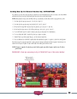
Photo Eye N/C contact monitoring -
1. Verify that SW1 dip switch 10 is ON press down on the right hand
side.
2. Verify that dip switch SW1 switch 7 or 8 (photo eye monitor) is ON
press down on the right hand side. Turn ON the ones being used.
3. Turn dip switch SW1 3 and 4 OFF. Allows power to be applied to
photo eye.
4. Press and hold the LED indicator button located on the control
board.
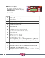
5. Verify that LD4 or LD5 LED (Photo eye N/C) located below J2 on the
control board is ON.
6. If not verify alignment between photo eye transmitter and receiver.
Correct if necessary.
7. If not then check wire connection from photo eye for proper
connection.
8. If LD4 or LD5 are ON verify that the Led goes OFF when photo eye
beam is broken.
9. If LED does not turn OFF when beam is broken then photo eye is
bad.
4. Gate will not
automatically close
NOTE:
If SW1 switch 1 is on then the gate should automatically close
from any position.
1. Locate the “Open/Close Command “ push button. Press the button
to verify that the gate will close. If gate closes correctly then proceed
to the steps below.
2. Verify that SW1 switch 1 is on. If not, turn it on and recheck gate
operation. If gate remains open, continue with step 3.
3. Locate the “LED Indicator” push button and depress and hold. While
pushing the button inspect the LED indicators located on the control
board (under the J2 Terminal Plug) and note which LED’s are on. If
LD1, LD2, LD6 or LD7 are ON then remove the wire from J2 for that
LED and cycle gate and verify auto close is working.
4. If so the device wired to J2 pin 3, 9, 10 or 11 that was disconnected
is bad.

