background image

digiset


5


Urma AG, Switzerland   www.urma.ch  

page 24


5.3    

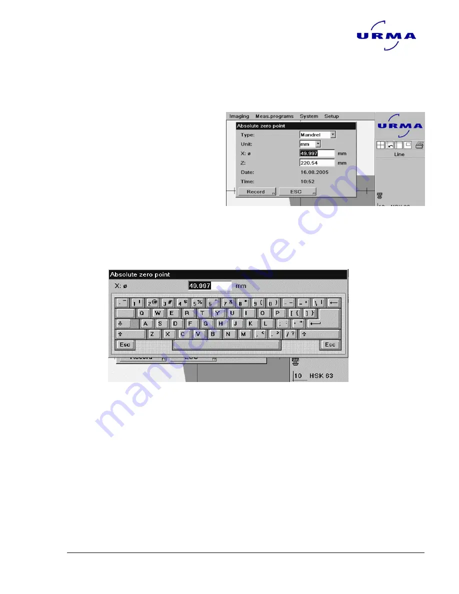
Input  by keyboard


The TCAM2 has no keyboard .  If you have to enter alphanumerical strings in  
An entering field, than you have to position the cursor on this field and you press  
The right bottom of your mouse. 


Example set absolute zero point 
 
When the cursor is set to the field 
X  ( white digits in a blue field) 
You press the right bottom on your  
Mouse  


It will open a window with the keyboard  


With the cursor you can now klick on the bottoms of the keyboard and in this way 
enter the alphanumerical strings.  
 
When you press ENTER the string will be written to the entering field and the key-
board will be closed. 


Содержание Digiset 5

Страница 1: ...Urma Digiset 5 USERMANUAL Version 1 0 e...

Страница 2: ...l Furthermore Urma AG hereby disclaim all warranties any legal responsibility or any liability for consequential damages arising from the incorrect use of the hardware and or software The layout or de...

Страница 3: ...NG DIGISET 5____________________________________________ 18 5 1 1 Menu bar Main menu ___________________________________________________ 19 5 1 2 Live picture _________________________________________...

Страница 4: ...ut________________________________________________________________ 40 7 4 6 Show list ______________________________________________________________ 40 8 IMAGING ______________________________________...

Страница 5: ...alysis devices and colour LCD Telecentric CMOS camera Telecentric LED light Desk top power pack USER manual on CD ROM Quick start manual outside of the wood box Dustcover Certification of conformity a...

Страница 6: ...vant geometrical data The object to be measured is displayed as a live picture on the bright 10 4 screen as well as the geometrical data automatically calculated for the object and the read ings of t...

Страница 7: ...for the components connection data to supply power to the equipment 3 The guarantee does not cover any damage to the imaging components caused by using your own power supply 4 The TCAM2 must be connec...

Страница 8: ...ient protection against dangerous electromagnetic radiation for the environment This applies as long as the product has been fitted and used in accordance with the instructions It is also necessary fo...

Страница 9: ...d with accessories Carefully unpack these accessories first Pic 2 1 3 Loosen the locking screws at the bottom of the wood box marked with black colour 1 4 You can now lift the frame of the box vertica...

Страница 10: ...mm 4x4x8 in 3 Carefully flip the Digiset as shown in Pic 4 make sure no parts get damaged 4 Take the metal frame and put in the cable binder as shown in Pic 5 and 5a it is difficult to put them in aft...

Страница 11: ...e pluged correctly 8 Connect the unit with the transformer and put the power cord to the power supply 9 Remove the security screw from the top of the tower 10 Switch on the unit and start with the bas...

Страница 12: ...and the object to be measured for example a tool cutting edge This measurement is preset by the design and the production tolerances of the cam era tube shield lens The working distance must be set f...

Страница 13: ...e as horizontal as possi ble and within the horizontal tolerance range marked by 2 purple lines You access the operating mode for setting the illumination using the following menu steps Main menu Sub...

Страница 14: ...you will see what the move ment of the print will cause with the greyscale lines You move the print until all greyscale lines are horizontal Potentiometer slotted head screws 4 If the greyscale lines...

Страница 15: ...gn camera The TCAM2 then displays a histogram that shows the deviation away from the vertical axis The displayed value for the angle should be less than 0 02 Procedure 1 Set the master mandrill on the...

Страница 16: ...tion bar into the Digiset spindle 2 Switch on the Digiset 3 Move the measuring arm in both axis 4 Move the measuring arm to the upper position A 5 Click SETUP on the menubar Corrections Parallel corre...

Страница 17: ...int absolute zero point it will appear the window on the left Enter the known dimensions of the master mandrill 2 Press on the Record bottom on this window and it will open a new Window showing 1 poin...

Страница 18: ...into three sections The menu bar is at the top of the screen Below this in the largest area of the screen the live picture of the object to be measured is displayed with cross hairs and various settin...

Страница 19: ...ure centre Range Measure method M0 Automatic M1 L1 M2 L2 M3 PX M4 PZ M5 L1 PX M6 L2 PX M7 L1 PZ M8 L2 PZ M9 L1 L2 M10 L1 L2 PX M11 L1 L2 PZ M12 PX PZ Meas programs Line Angle Radius With Measure centr...

Страница 20: ...the Preset and Maximum operating modes these cross hairs remain so that the tool reference for the whole measuring structure is retained Additional red measuring lines are created on the object s pro...

Страница 21: ...rea where the TCAM2 carries out contour measurements so that the most interesting area can be selected even with objects that have complex contours The size of the analysis window can be changed as re...

Страница 22: ...icon with the identity number and name of the selected tool shown in clear text The stored tools can be displayed directly by clicking on the tool icon Tool reference symbol with tool reference numbe...

Страница 23: ...ue relating to the selected tool refer ence Difference Current counter value relating to the selected tool refer ence including nominal values Increment The reading is reset to 0 000 Diameter The curr...

Страница 24: ...The right bottom of your mouse Example set absolute zero point When the cursor is set to the field X white digits in a blue field You press the right bottom on your Mouse It will open a window with th...

Страница 25: ...stem information and you can license soft ware extensions that need to be paid for by entering a new licence number Make sure you don t lose the licence number If you lose the licence number the syste...

Страница 26: ...ite You access this operating mode using the following menu steps Main menu Sub menu 1 Sub menu 2 Setup Imaging Black White Here you can decide whether an object and its contour are displayed in colou...

Страница 27: ...his menu item works as a toggle function and changes the setting of a normal tool with cuts outwards to an inverse tool with cuts inwards such as is the case with bell tools The Inverse tool setting o...

Страница 28: ...meter gives the maximum permissible deviation of the edge values from the ideal shape of the circle The deviation can be varied from 0 m to 100 m The standard setting default is 45 m 6 3 Serial interf...

Страница 29: ...fine the interface for an output and the corresponding formats for labels or lists For labels the required format can also be selected from a format template catalogue The USB port is available as a s...

Страница 30: ...eparately The third axis Axis 3 is optionally You access these operating modes using the following menu steps Main menu Sub menu 1 Sub menu 2 Setup Counter Axis 1 Axis 2 Axis 3 Parameters that must be...

Страница 31: ...he system with parallel correction 6 6 3 Absolute zero point optional You access this operating mode using the following menu steps Main menu Sub menu 1 Sub menu 2 Setup Corrections Absolute zero poin...

Страница 32: ...the loaded language modules 6 8 Password Important system settings can be protected from unauthorised access by allocating a password You access this operating mode using the following menu steps Mai...

Страница 33: ...rt You access this operating mode using the following menu steps Main menu Sub menu 1 Setup Date and time 6 10 Maintenance and service To maintain the system it is sometimes necessary to load the fact...

Страница 34: ...equired tool reference 7 1 2 Manage tool references This menu item gives you the option of creating and saving new tool references changing and deleting stored tool references and displaying a list of...

Страница 35: ...entering a new tool reference 7 1 2 4 Show tool reference list After selecting the Show list operating mode a window opens with a selection list of the saved tool references and the buttons explained...

Страница 36: ...2 Manage tools This menu item gives you the option of creating and saving new tools changing and deleting stored tools and displaying a list of all tools You access this operating mode using the foll...

Страница 37: ...which the chan ges can be made opens just as it does when entering a new tool 7 2 2 4 Show list of tools After selecting the Show list operating mode a window opens with a selection list of the saved...

Страница 38: ...e buttons shown have the following functions Edit The entries on the tool selected in the tool list can be chan ged New The tool selected in the tool list will be measured again Delete The tool marked...

Страница 39: ...no more than five stored formats post processor formats 2 After selecting the desired output format the corresponding input mask opens Enter the logarithm data here This input mask doesn t have to ap...

Страница 40: ...s are added 7 4 5 Output The measurement range is transferred as a controlled output format to a machine tool Either the serial interface RS232 or the Ethernet effects the transfer If several machine...

Страница 41: ...ct to be measured on its support sets the greatest deviation and thus the focus level 4 While the object is being turned the test LED in the upper left corner turns green as soon as the measurement is...

Страница 42: ...he object to be measured is within the focussing area the ad justment bars are displayed The TCAM2 automatically determines the best measuring procedure and the test LED goes green 9 Move the edge of...

Страница 43: ...e button Procedure 1 Move the object into the camera s visual range 2 If the relevant contour of the object is not clear select the Range operating mode and using the mouse make it the required size a...

Страница 44: ...alternative measuring method is required it is possible to enter the measuring procedure manu ally by pressing the button Procedure 1 Move the object into the camera s visual range 2 If the relevant...

Страница 45: ...o the cross hair origin point when both pointers are in the middle of the green area You access this operating mode using the following menu steps Main menu Sub menu 1 Imaging Measure centre Selecting...

Страница 46: ...5 automatically calculates the highest deviation position and creates the red measuring lines vertically or hori zontally 8 3 1 2 Line or angle measurement Line measurement determines and analyses on...

Страница 47: ...etermined by the TCAM2 M1 L1 Line 1 measurement M2 L2 Line 2 measurement M3 PX Point X measurement M4 PZ Point Z measurement M5 L1 PX Line 1 and point X measurement M6 L2 PX Line 2 and point X measure...

Страница 48: ...r clockwise within the analysis win dow 8 3 2 2 Line 2 measurement L2 Line 2 is determined Dark to light border counter clockwise within the analysis win dow 8 3 2 3 Point X measurement PX The maximum...

Страница 49: ...maximum X deviation and line 2 are determined The re sults then show the intersection point 8 3 2 7 Line 1 Point Z measurement L1 PZ The maximum Z deviation and line 1 are determined The re sults then...

Страница 50: ...exactly in the middle 8 3 2 11 Line 1 Line 2 Point Z measurement L1 L2 PZ The horizontal axis is touched at one point and shown as a red measuring line The intersection point of the two other measur i...

Страница 51: ...ill be taken as the display and analysis point If there is no edge nearby the precise posi tion of the mouse pointer will be taken Procedure 1 Select Line 2 Move the mouse pointer to the desired posit...

Страница 52: ...e TCAM2 looks for the next edge pixel as an analysis point Procedure 1 Select Radius 2 Move the mouse pointer to the desired position and left click The TCAM2 sets the first analysis point here 3 Move...

Страница 53: ...le 52 Line 51 Radius 52 With measure centre 52 Measuring line 21 Measuring method Fixed axis 42 Maximum 43 Measure centre 45 Preset 44 Measuring procedure Description of principal procedures 46 Detail...

Страница 54: ...digiset 5 Urma AG Switzerland www urma ch page 54 10 Appendix 1 Password 111111 Password Factory setting...

Отзывы: