GB
F
D
42
I
2.4
2.5
2.6
1
2
23
A
B
C
D
PREDISPOSIZIONE
MACCHINA
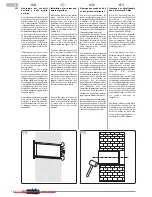
Il climatizzatore viene assemblato
in fabbrica con la predisposizione per
il montaggio nella parte bassa della
parete. L’uscita dell’aria in questo
caso si trova nel lato superiore
dell’apparecchio ed è predisposto con
l’applicazione con alette direzionali
mobili.
SOSTITUZIONE CONFIGURA-
ZIONE DEFLETTORI MOBILI
CON GRIGLIE
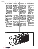
OPERAZIONE DA COMPIERE
CON MACCHINA SPENTA E
ALIMENTAZIONE ELETTRICA
SCOLLEGATA.
Dalla configurazione con cui la
macchina viene consegnata è
possibile passare a quella con le
griglie di direzione flusso aria regolabili
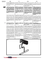
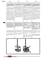
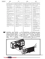
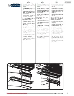
manualmente (fig. 23).
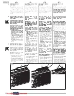
- Staccare dai relativi supporti le due
alette flap (fig. 23rif. A), sfilando
prima un perno e poi quello dalla
parte opposta.
- Infilare la griglia (fig. 23 rif. B)
inserendola negli appositi agganci
- infilare i due pattini di
trascinamento alette (fig. 23 rif.
C).
ATTENZIONE centrare le alette
inferiori (fig. 23 rif. D) nei due
pattini.
PREDISPOSIZIONE INSTALLA-
ZIONE PARTE ALTA PARETE
OPERAZIONE DA COMPIERE
CON MACCHINA SPENTA E
ALIMENTAZIONE ELETTRICA
SCOLLEGATA.
Nella parte superiore della
macchina smontare:
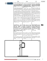
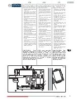
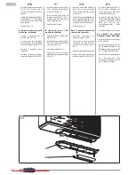
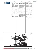
- Estrarre dalla sua sede il
telecomando (fig. 24 rif. A)
- Staccare dai relativi supporti le due
alette flap (fig. 24 rif. B), sfilando
prima un perno e poi quello dalla
parte opposta.
PROVISIONS FOR MACHINE
INSTALLATION
The air-conditioner is assembled in
the factory with fittings for the
installation onto the lower part of the
wall. In this case, the air outlet is in
the upper side of the unit and
equipped with movable directional
fins.
REPLACEMENT OF THE
MOVING FLAPS
CONFIGURATION WITH
GRILLES
OPERATION TO BE
PERFORMED WHEN THE
MACHINE IS SWITCHED OFF
AND THE POWER SUPPLY IS
DISCONNECTED.
The unit's configuration at delivery
can be replaced with manually
adjustable air flow direction grilles
(fig. 23).
- Remove the two flaps from the
relevant supports (fig. 23 ref. A),
extracting a pin first, then the pin
on the opposite side.
- Fit the grille (fig. 23 ref. B),
inserting it into the fasteners
provided
- Fit the two dragging pads (fig. 23
ref. C).
ATTENTION: the lower flaps must
be centered (fig. 23 ref. D) into
the two pads.
PROVISIONS FOR THE
INSTALLATION ONTO THE
UPPER PART OF THE WALL
OPERATION TO BE
PERFORMED WHEN THE
MACHINE IS SWITCHED OFF
AND THE POWER SUPPLY IS
DISCONNECTED.
In the upper part of the
machine disassemble:
- Extract the remote control from
its seat (fig. 24 ref. A)
- Remove the two flaps from the
relevant supports (fig. 24 ref. B),
extracting a pin first, then the pin
on the opposite side.
PRÉPARATION DE LA
MACHINE
Le climatiseur est assemblé à l'usine
avec la préparation pour le montage
dans la partie basse du mur. Dans
ce cas, la sortie d'air se trouve sur le
côté supérieur de l'appareil et il est
préparé avec l'application des ailettes
directionnelles mobiles.
REMPLACEMENT DE LA
C O N F I G U R A T I O N
DÉFLECTEURS MOBILES PAR
DES GRILLES
OPÉRATION À EFFECTUER
LORSQUE LA MACHINE EST
ÉTEINTE ET QUE
L'ALIMENTATION ÉLECTRIQUE
EST DÉBRANCHÉE.
À partir de la configuration avec
laquelle la machine est livrée, on peut
passer à la configuration avec les
grilles de direction du flux d'air
réglables manuellement (fig. 23).
- Détacher les deux ailettes flap des
supports relatifs (fig. 23réf. A), en
retirant en premier un axe et
ensuite celui du côté opposé.
- Introduire la grille (fig. 23 réf. B)
en l'insérant dans les crochets
prévus à cet effet.
- introduire les deux patins
d'entraînement des ailettes (fig.
23 réf. C).
ATTENTION centrer les ailettes
inférieures (fig. 23 réf. D) dans
les deux patins.
PREPARATION POUR
L'INSTALLATION DANS LA
PARTIE HAUTE DU MUR
OPÉRATION À EFFECTUER
LORSQUE LA MACHINE EST
ÉTEINTE ET QUE
L'ALIMENTATION ÉLECTRIQUE
EST DÉBRANCHÉE.
Dans la partie supérieure de
la machine démonter :
- Extraire la télécommande de son
logement (fig. 24 réf. A)
- Détacher les deux ailettes flap des
supports relatifs (fig. 24 réf. B),
en retirant en premier un axe et
ensuite celui du côté opposé.
VORBEREITUNG DES
GERÄTS
Die Klimaanlage wird im Werk
zusammengebaut und für die niedrige
Wandmontage vorbereitet. Der
Luftausgang befindet sich in diesem
Fall am Oberteil des Geräts und ist
für die Montage einstellbarer
Luftleitlamellen vorbereitet.
FLAT KONFIGURATION MIT
EINSTELLBAREN LAMELLEN
GITTER ERSETZEN
DER VORGANG DARF NUR BEI
ABGESCHALTETEM GERÄT
UND ABGETRENNTER
S T R O M V E R S O R G U N G
VORGENOMMEN WERDEN.
Die Konfiguration des gelieferten
Geräts kann geändert bzw. es können
die von Hand einstellbaren
Luftleitgitter angebracht werden (Abb.
23).
- Die beiden Flap-Flügel (Abb. 23,
Ref. A) aus ihren Halterungen
nehmen indem zuerst der eine
Stift dann der Stift an der
entgegengesetzten Seite
herausgezogen werden.
- das Gitter (Abb. 23 Ref. B) in die
entsprechenden Haken einsetzen
- die beiden Gleitschuhe der
Lamellen (Abb. 23 Ref. C)
einsetzen
ACHTUNG die unteren Lamellen
(Abb. 23 Ref. D) im Verhältnis zu
den beiden Schuhen zentrieren.
VORBEREITUNG ZUR
WANDINSTALLATION UNTER
DER DECKE
DER VORGANG DARF NUR BEI
ABGESCHALTETEM GERÄT
UND ABGETRENNTER
S T R O M V E R S O R G U N G
VORGENOMMEN WERDEN.
Am Oberteil des Geräts
Folgendes abmontieren:
- Die Fernbedienung aus ihrem Sitz
nehmen (Abb. 24 Ref. A)
- Die beiden Flap-Flügel (Abb. 24, Ref.
B) aus ihren Halterungen nehmen
indem zuerst der eine Stift dann der
Stift an der entgegengesetzten Seite
herausgezogen werden.
Downloaded from AC-Manual.com Manuals
Содержание Gamma Sky
Страница 110: ...Downloaded from AC Manual com Manuals...

