GB
F
D
38
I
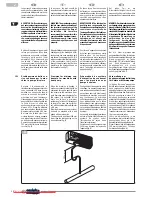
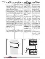
E’ possibile procedere
all’allacciamento mediante un cavo
incassato nella parete come in
posizione indicata nella dima. In que-
sto caso è necessario:
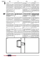
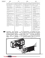
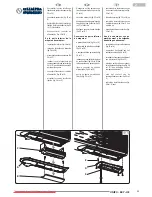
- sfilare i 6 tappi sulla copertura
frontale (fig. 19 rif. A)
- svitare le sei viti di fissaggio della
copertura (fig. 19 rif. B)
- rimuovere la copertura frontale
(fig. 19 rif. C)
- rimuovere il coperchio della
scatola elettrica (fig. 19 rif. D)
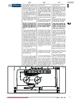
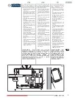
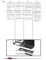
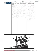
- svitare il morsetto passacavo (fig.
20 rif. A)
- svitare le viti di bloccaggio cavo
della morsettiera (fig. 20 rif. B)
- appoggiare sul retro della
macchina una zeppa in legno (fig.
20 rif. C)
- sfilare il cavo presente
- infilare il nuovo cavo seguendo il
medesimo percorso
- rimuovere la zeppa in legno sul
retro della macchina
- bloccare i tre poli del cavo nella
morsettiera e stringere le viti
- bloccare il cavo con il morsetto
(fig. 20 rif. B)
- chiudere la protezione della
scheda (fig. 19 rif. D)
- rimontare la copertura frontale
della macchina con le sei viti
- chiudere i fori con i sei tappi (fig.
19 rif. A).
AVVERTENZA: queste
operazioni devono essere
svolte con la macchina già
posizionata sulla staffa,
quindi leggete attentamen-
te anche le istruzioni se-
guenti prima di
completare l’allacciamento
elettrico.
The connection can be performed
with a cable enclosed in the wall, in
the position indicated in the template.
In this case it is necessary to:
- remove the 6 caps on the front
cover (fig. 19 ref. A)
- unscrew the six fixing screws of
the cover (fig. 19 ref. B)
- remove the front cover (fig. 19 ref.
C)
- remove the cover of the electrical
box (fig. 19 ref. D)
- unscrew the cable clamp (fig. 20
ref. A)
- unscrew the cable fixing screws
of the terminal board (fig. 20 ref.
B)
- place a wooden wedge on the back
of the unit (fig. 20 ref. C)
- extract the cable
- insert the new cable following the
same path
- remove the wooden wedge from
behind the unit
- block the three poles of the cable
in the terminal board and tighten
the screws
- block the cable with the clamp (fig.
20 ref. B)
- close the protection of the board
(fig. 19 ref. D)
- remount the front cover of the
machine with the six screws
- plug the holes with the six caps
(fig. 19 ref. A)
C A U T I O N: t h e s e
o p e r a t i o n s s h o u l d b e
p e r f o r m e d w i t h t h e
m a c h i n e a l r e a d y
positioned on the bracket.
R e a d t h e i n s t r u c t i o n s
c a r e f u l l y b e f o r e
c o m p l e t e l y t h e e l e c t r i c
connection.
Il est possible d'effectuer le
branchement avec un câble encastré
dans le mur selon la position indiquée
par le gabarit. Dans ce cas, il faut :
- retirer les 6 bouchons du couvercle
avant (fig. 19 réf. A)
- dévisser les six vis de fixation du
couvercle (fig. 19 réf. B)
- enlever le couvercle avant (fig. 19
réf. C)
- enlever le couvercle de la boîte
électrique (fig. 19 réf. D)
- dévisser la borne serre-fils (fig.
20 réf. A)
- dévisser le vis de blocage du câble
de la plaque à bornes (fig. 20 réf.
B)
- mettre une cale en bois à l'arrière
de la machine (fig. 20 réf. C)
- retirer le câble présent
- passer le nouveau câble en
suivant le même chemin
- enlever la cale en bois à l'arrière
de la machine
- bloquer les trois pôles du câble
dans la plaque à bornes et serrer
les vis
- bloquer le câble avec la borne (fig.
20 réf. B)
- fermer la protection de la carte
(fig. 19 réf. D)
- remonter le couvercle avant de la
machine avec les six vis
- fermer les trous avec les six
bouchons (fig. 19 réf. A).
AV E R T I S S E M E N T: C e s
o p é r a t i o n s d o i v e n t ê t r e
f a i t e s a v e c l a m a c h i n e
d é j à p o s i t i o n n é e s u r l a
b r i d e , d o n c l i s e z
a t t e n t i v e m e n t l e s
i n s t r u c t i o n s s u i v a n t e s
a v a n t d e c o m p l é t e r l e
branchement électrique.
Kann der Anschluss über ein in der
Wand versenktes Kabel in der von
der Schablone angegebenen Position
erfolgen. In diesem Fall
folgendermaßen vorgehen:
- die 6 Stöpsel an der
Frontabdeckung (Abb. 19 Ref. A)
abnehmen
- die sechs Befestigungsschrauben
der Abdeckung (Abb. 19 Ref. B)
abschrauben
- die Frontabdeckung (Abb. 19 Ref.
C) abnehmen
- den Dosendeckel (Abb. 19 Ref.
D) abnehmen
- die Kabeldurchgangsklemme
(Abb. 20 Ref. A) abschrauben
- die Befestigungsschrauben der
Kabelklemme (Abb. 20 Ref. B)
abschrauben
- auf die Rückseite des Geräts
einen Holzscheit legen (Abb. 20
Ref. C)
- das vorhandene Kabel
herausziehen
- das neue Kabel entlang derselben
Strecke verlegen
- den Holzscheit an der Rückseite
des Geräts entfernen
- die drei Kabelpole in der
Klemmleiste blockieren und die
Schrauben festziehen
- die Kabeldurchgangsklemme
(Abb. 20 Ref. B) blockieren
- die Schutzklappe der Karte (Abb.
19 Ref. D) anbringen
- die Frontabdeckung des Geräts
mit den sechs Schrauben wieder
montieren
- die Löcher mit den sechs Stöpseln
(Abb. 19 Ref. A) schließen
HINWEIS: Diese Arbeits-
gänge sind bei einem an
d e r W a n d h ä n g e n d e n
G e r ä t d u r c h z u f ü h r e n .
Daher sind vor dem elek-
trischen Anschluss auch
die folgenden Anweisun-
g e n a u f m e r k s a m
durchzulesen.
19
A
B
C
D
2
Downloaded from AC-Manual.com Manuals
Содержание Gamma Sky
Страница 110: ...Downloaded from AC Manual com Manuals...

