Exhaust filters (Ref. 120) should be checked monthly.
A pressure gauge (Ref. 90) is supplied with your R5
vacuum pump as part of the oil fill plug. This gauge has
a green field and a red field. A pressure within the
green field would indicate normal pressure. Any pres-
sure in the red field (for a continuos period of time)
requires an immediate change of the exhaust filter(s).
Every nine (9) to twelve (12) months, or as necessary,
replace the exhaust filter elements. The service life of
the exhaust filters varies widely with pump application.
It is only necessary to change the filters when the ele-
ments become clogged with foreign material or burned
oil. Indications of clogged filters are smoke and oil mist
coming from the pump exhaust or higher than normal
motor current.
In order to replace the exhaust filters, unscrew the
screws and washers (Ref. 142/143) from the exhaust
cover plate (Ref. 140). Remove the cover plate and
gasket (Ref. 141).
Remove the distance pin (Ref. 137), the baffle strainer
(Ref. 130) and the sheet metal plate (Ref. 136).
Remove the discharge filter assembly by unscrewing
the nut (Ref. 134) and removing the lockwasher (Ref.
132). Carefully slide the assembly out of the exhaust
box (Ref. 75). Stand the filter assembly up on a clean
flat surface.
To have access to the individual filters, unscrew the two
cylinder cover screws (Fig. 126), and remove the two
lockwashers (Ref. 128) and the exhaust filter grip plate
(Ref. 115).
Remove the exhaust filters (Ref. 120) and O-rings (Ref.
121). Remove the filter support (Ref. 118) and O-rings
(Ref. 119).
Replace the support and O-rings with new ones. Make
sure that the O-rings are fitted securely and that the fil-
ter elements (Ref. 120) fit securely into the depressions
on the filter support (Ref. 118). The indicating arrow on
each element must be pointing upward toward the top
of the exhaust box after the assembly has been
installed.
Carefully position the filter support tube (Ref. 133)
between the exhaust filter grip (Ref. 115) and the filter
support without displacing the filters from their seated
position in the filter support. Install the two lockwashers
(Ref. 128) and two screws (Ref. 126).
Insert the support and filter assembly into the exhaust
box using the stud (Ref. 131) as a guide. The stud
should slide through the hole in the support (Ref. 133).
Secure the assembly with the lockwasher (Ref. 132)
and hexagon nut (Ref. 134).
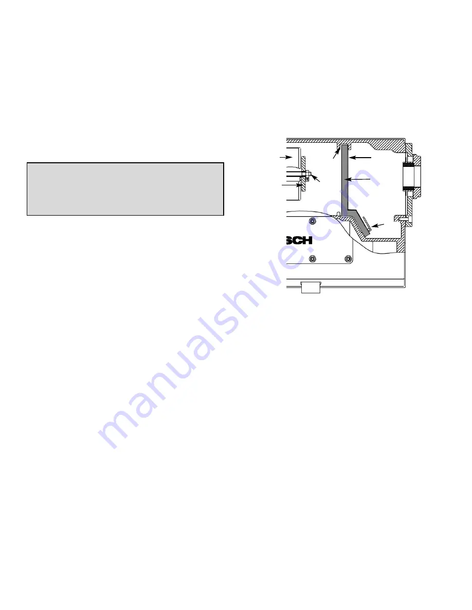
Reinstall the sheet metal plate (Ref. 136) and the baffle
strainer (Ref. 130) into the guide track of the exhaust
box (see Fig. 4). Press to the bottom of the exhaust
box. Make sure that the baffle strainer touches all sides
of the exhaust box. Insert the distance sleeve (Ref.
137) into the two grooves. This holds the sheet metal
plate and baffle strainer in place.
Inspect the exhaust box end cover gasket (Ref. 141) for
damage and replace if damaged. With the gasket in
place, secure the exhaust cover end plate (Ref. 140) to
the exhaust box using eight hex head cap screws (Ref.
142) and eight lockwashers (Ref. 143).
To field test an exhaust filter element, remove it from
the pump, allow it to cool, clean the sealing end (or O-
ring end), and use compressed air to blow through the
element. Apply approximately 3 to 6 psi, which is the
maximum allowable operating pressure across the fil-
ter.
Use a shop rag to seal off the connection between the
air hose and the filter.
If you can blow through it, the element is good. If not,
discard it and install a new one. The filter cannot be
cleaned successfully. Visually inspect the filter element
for cracks.
Reinstall the filter elements as described previously.
3.4
Inlet Flange
The standard inlet flange assembly contains an inlet
screen (Ref. 261) which may require occasional clean-
ly. The frequency of cleaning can only be determined
8
Fig. 4 - Exhaust Filters and Strainer
Track
136
130
137
120
115
134
CAUTION: Excessively contaminated and/or
clogged exhaust filters could possibly lead
to elevated pump temperatures which
could, under certain circumstances, cause
the lubricating oil to self-ignite.
Содержание ULTRAVAC 2100
Страница 2: ......
Страница 81: ......
Страница 90: ...9 ...
Страница 91: ...10 ...
Страница 93: ...12 13 ...
Страница 101: ...21 Maximum oil temperature with 80 F ambient temperature and no supplemental oil cooling ...
Страница 102: ...22 ...
Страница 105: ......
Страница 120: ...RA 0165 0205 0255 0 0305 D Ref BMC Dwg T111 911 728 D 15 Fig 5 Exploded View Drawing of Pump ...


