Page 57
J-Series Data Radio – User Manual
Introduction
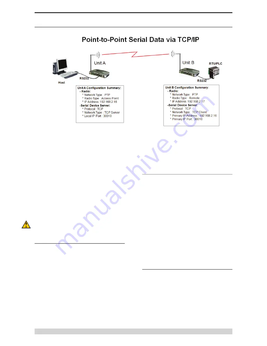
Point to Point connectivity using the TCP/IP mode of the
embedded J-Series terminal servers is useful for PTP (Point to
Point) serial link requiring high reliability data delivery.
In PTP Serial via TCP/IP two unique types of J-Series configuration
are required. One J-Series must be configured as the TCP Server.
The other J-Series must be configured as a TCP Client. Any
J-Series device (Access Point, Bridge or Remote) can function as
either a TCP server or client.
More information on PTP Serial via TCP/IP can be found in Part D
of this user manual.
The following information will guide you through the minimum
steps required to configure this feature in the J-Series. Refer to the
HTML programmer for more information about each item.
Please ensure you have already configured the J-Series radios
for PTP mode as described in the Point to Point Quick Start
Guide using the IP addresses as defined in the image above. The
following procedure assumes this has already been done.
1 - TCP Server Configuration (Unit A)
Connect your browser to the J-Series configuration web page of
Unit A (192.168.2.16) and select to the “Configuration” page and
then select the “Serial Port A” option.
(a) Ensure the Mode is configured to be “Serial Device Server”
(b) Ensure the Character Layer matches the configuration of the
external serial device you are connecting to the J-Series Serial
Port. The default is 9600,8,N,1.
(c) Ensure the Packet Layer is set to “Standard”
(d) Ensure the Protocol is configured to be “TCP”
(e) Ensure the Network Type is configured to be “TCP Server”
(f) Ensure the Local IP Port is configured to be “30010”
(g) Ensure the Inactivity Timeout is set to “5” seconds.
Point to Point - TCP Serial Device Server Setup Guide
Click on Activate Configuration.
Once the web browser has activated the new configuration and
then returned to the Configuration page, the configuration of the
TCP Server is now complete. The next step is to configure the TCP
Client.
2 - TCP Client Configuration (Unit B)
Connect your browser to the J-Series configuration web page of
Unit B (192.168.2.17) and select to the “Configuration” page and
then select the “Serial Port A” option.
Repeat the steps as shown above in “1 - TCP Server
Configuration” with the exception of the following steps.
Ensure the Network Type is configured to be “TCP Client”
Ensure the Primary IP Address is configured to be the IP address
of Unit A which is “192.168.2.16”
Ensure the Primary IP Port is configured to be “30010”
Ensure the Secondary IP Address & Port is blank.
Click on Activate Configuration.
Once the web browser has activated the new configuration and
then returned to the Configuration page, the configuration of the
TCP Client is now complete.
3 - RS-232 Final Testing
The Point to Point via TCP Serial connectivity is now complete.
The RS-232 link can be tested using an RS-232 Serial Packet
Test Program such as LinkTest or by connecting your RS-232
application.
The PortA/B LED status can also be used to diagnose the PTP
via TCP Serial Link. A flashing RED LED means that RS-232 data
is being sent into the radio for transmission. A flashing GREEN
LED means that RS-232 data is being received from the link and
presented to the port.
Part G – Quick Start Guide
Содержание JR240
Страница 1: ...J Series Ethernet Radio User Manual ...


