Page 54
J-Series Data Radio – User Manual
Issue 09-10
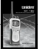
Typical Radio Setup
This is the sequence of steps required for configuring two J-Series
in a point-to-point network. One will be configured as an Access
Point and the other as a Remote.
Step 1 - RF and DC power
connection
Connect a whip antenna to the ANT1 TNC connector of both
radios.
Ensure the whip antennas you are using are for the correct
frequency otherwise a high VSWR error may occur.
Check the DC polarity and ensure the DC voltage is between 10V
and 30V with a maximum current capacity of 1Amp (nom 500mA).
Incorrect polarity or excessive voltage may result in a blown fuse!
Step 2 - Power Up Radios
Apply DC power to the radios. The “Pwr” LED should now be solid
GREEN.
Wait 45 seconds for the boot up sequence to be complete. This will
be indicated when the Sync/NoRx LED flashes at a rate of once a
second.
Part G – Quick Start Guide
Point to Point Ethernet Link Setup
Step 3 - Preliminary Configuration
IP Address and Factory Default
The default IP address of the J-Series radio is 192.168.2.15. To
configure the J-Series radio you must know the IP address of
the radio. If you are uncertain of the current IP programmed into
the radio you will need to reset the radio configuration to factory
default.
This can be done by powering up the radio (wait 45 seconds),
depress the factory default switch using a paper clip or similar
thin blunt wire and keep the switch depressed for 5 seconds. All
5 LEDs will illuminate solid GREEN indicating the radio will return
to factory default settings. Please wait 30 seconds with the factory
default reset process to occur.
Ethernet Configuration Ping Test
Connect your PC LAN Port to one of the Ethernet Ports (LAN1 or
LAN2).
The corresponding Link/Activ LAN LED will illuminate continuously
Green. If data is being transferred, the Link/Activ LAN LED may
also flash Amber.
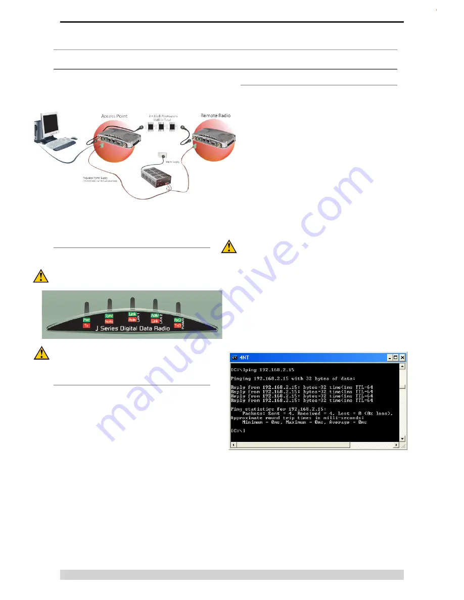
To verify your PC can communicate with the J-Series you should
first use the “ping” utility to test the connection to the Ethernet Port.
Open up a command window on your PC by going to the “Start”
-> Run and typing “CMD” then OK. Then type “ping 192.168.2.15”
which is the default address of the radio.
If both the radio and PC have their LAN port connection and
configuration correct, the radio will respond to the ping as shown
above. If this is not the case, check you network settings as
described in Part F - Quick Reference Guide.
Содержание JR240
Страница 1: ...J Series Ethernet Radio User Manual ...