Control panel SP231
Configuration of control panel operation
©1997-2015 Trikdis
39
www.trikdis.com
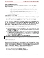
6.13.1
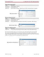
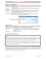
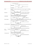
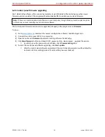
PGM output operation descriptions
PGM output mode
Description
Bell
Output for connection of audible sounder (siren).
After the alarm system actuation a continuous or pulse (fire) signal is generated.
Buzzer
Output for connection of audio indicator.
After the alarm system activated a pulse signal is generated within Exit Delay time,
and continuous signal - within Entry Delay time or when the alarm system is
disturbed. When the alarm system is turned off, operates like keyboard buzzer.
Flash
Output for connection of light indicator.
When the alarm system is on, a continuous signalis generated, and if the alarm
system is disturbed - pulse signal. Signal is terminated by turning off the alarm
system.
System State
Output for connection of light indicator of the alarm system status.
Within Exit Delay time a pulse signal is generated, and when the alarm system
activated
–
continuous. Signal is terminated by turning off the alarm system.
Ready
Output for connection of light indicator of input statuses.
If all zones are clear (none violated), a continuous signal is generated.
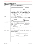
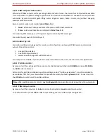
Remote Control
Output designed for connection of electrical devices which will be controlled by
SMS message or phone call
a) control by SMS message
Pulse mode:
Level mode:

