Page 53
TMP86PM29BUG
5.2
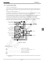
Port P2 (P22 to P20)
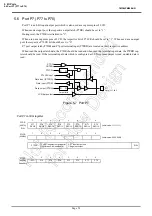
Port P2 is a 3-bit input/output port.
It is also used as an external interrupt, a STOP mode release signal input, and low-frequency crystal oscillator con-
nection pins. When used as an input port or a secondary function pins, respective output latch (P2DR) should be set
to “1”.
During reset, the P2DR is initialized to “1”.
A low-frequency crystal oscillator (32.768 kHz) is connected to pins P21 (XTIN) and P22 (XTOUT) in the dual-
clock mode. In the single-clock mode, pins P21 and P22 can be used as normal input/output ports.
It is recommended that pin P20 should be used as an external interrupt input, a STOP mode release signal input, or
an input port. If it is used as an output port, the interrupt latch is set on the falling edge of the output pulse.
P2 port output latch (P2DR) and P2 port terminal input (P2PRD) are located on their respective address.
When read the output latch data, the P2DR should be read and when read the terminal input data, the P2PRD reg-
ister should be read. If a read instruction is executed for port P2, read data of bits 7 to 3 are unstable.
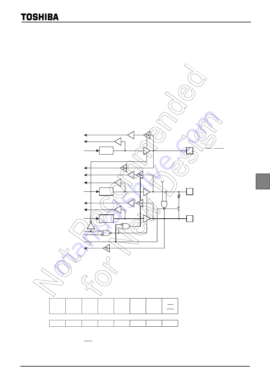
Figure 5-3 Port P2
Note: Port P20 is used as
STOP
pin. Therefore, when stop mode is started, OUTEN does not affect to P20, and P20 becomes
High-Z mode.
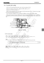
Port P2 control register
P2DR
(0002H)
R/W
7
6
5
4
3
2
1
0
P22
XTOUT
P21
XTIN
P20
INT5
STOP
(Initial value: **** *111)
7
6
5
4
3
2
1
0
P2PRD
(0009H)
Read only
P22
P21
P20
! "#"
$ %
$ %
$ %
Содержание TLCS-870/C Series
Страница 1: ...8 Bit Microcontroller TLCS 870 C Series TMP86PM29BUG ...
Страница 6: ...TMP86PM29BUG ...
Страница 7: ...Revision History Date Revision 2007 10 11 1 First Release 2008 8 29 2 Contents Revised ...
Страница 9: ......
Страница 15: ...vi ...
Страница 19: ...Page 4 1 3 Block Diagram TMP86PM29BUG 1 3 Block Diagram Figure 1 2 Block Diagram ...
Страница 23: ...Page 8 1 4 Pin Names and Functions TMP86PM29BUG ...
Страница 48: ...Page 33 TMP86PM29BUG ...
Страница 49: ...Page 34 2 Operational Description 2 3 Reset Circuit TMP86PM29BUG ...
Страница 61: ...Page 46 3 Interrupt Control Circuit 3 8 External Interrupts TMP86PM29BUG ...
Страница 81: ...Page 66 6 Watchdog Timer WDT 6 3 Address Trap TMP86PM29BUG ...
Страница 135: ...Page 120 10 8 Bit TimerCounter TC5 TC6 10 1 Configuration TMP86PM29BUG ...
Страница 145: ...Page 130 11 Asynchronous Serial interface UART 11 9 Status Flag TMP86PM29BUG ...
Страница 165: ...Page 150 13 10 bit AD Converter ADC 13 6 Precautions about AD Converter TMP86PM29BUG ...
Страница 183: ...Page 168 15 LCD Driver 15 4 Control Method of LCD Driver TMP86PM29BUG ...
Страница 201: ...Page 186 18 Electrical Characteristics 18 9 Handling Precaution TMP86PM29BUG ...
Страница 203: ...Page 188 19 Package Dimensions TMP86PM29BUG ...
Страница 205: ......

