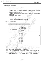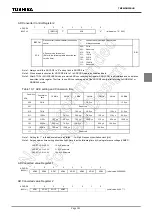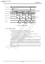
Page 135
TMP86PM29BUG
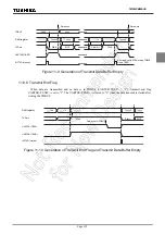
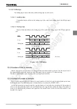
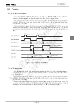
12.3.2 Shift edge
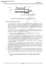
The leading edge is used to transmit, and the trailing edge is used to receive.
12.3.2.1 Leading edge
Transmitted data are shifted on the leading edge of the serial clock (falling edge of the
SCK
pin input/
output).
12.3.2.2 Trailing edge
Received data are shifted on the trailing edge of the serial clock (rising edge of the
SCK
pin input/out-
put).
Figure 12-5 Shift edge
12.4 Number of bits to transfer
Either 4-bit or 8-bit serial transfer can be selected. When 4-bit serial transfer is selected, only the lower 4 bits of
the transmit/receive data buffer register are used. The upper 4 bits are cleared to “0” when receiving.
The data is transferred in sequence starting at the least significant bit (LSB).
12.5 Number of words to transfer
Up to 8 words consisting of 4 bits of data (4-bit serial transfer) or 8 bits (8-bit serial transfer) of data can be trans-
ferred continuously. The number of words to be transferred can be selected by SIOCR2<BUF>.
An INTSIO interrupt is generated when the specified number of words has been transferred. If the number of
words is to be changed during transfer, the serial interface must be stopped before making the change. The number of
words can be changed during automatic-wait operation of an internal clock. In this case, the serial interface is not
required to be stopped.
Bit 1
Bit 2
Bit 3
*
321
3210
**
32
***
3
Bit 0
Shift register
Shift register
Bit 1
Bit 0
Bit 2
Bit 3
0
***
****
210
*
10
**
3210
(a) Leading edge
(b) Trailing edge
*
; Don’t care
SO pin
SI pin
SCK pin
SCK pin
Содержание TLCS-870/C Series
Страница 1: ...8 Bit Microcontroller TLCS 870 C Series TMP86PM29BUG ...
Страница 6: ...TMP86PM29BUG ...
Страница 7: ...Revision History Date Revision 2007 10 11 1 First Release 2008 8 29 2 Contents Revised ...
Страница 9: ......
Страница 15: ...vi ...
Страница 19: ...Page 4 1 3 Block Diagram TMP86PM29BUG 1 3 Block Diagram Figure 1 2 Block Diagram ...
Страница 23: ...Page 8 1 4 Pin Names and Functions TMP86PM29BUG ...
Страница 48: ...Page 33 TMP86PM29BUG ...
Страница 49: ...Page 34 2 Operational Description 2 3 Reset Circuit TMP86PM29BUG ...
Страница 61: ...Page 46 3 Interrupt Control Circuit 3 8 External Interrupts TMP86PM29BUG ...
Страница 81: ...Page 66 6 Watchdog Timer WDT 6 3 Address Trap TMP86PM29BUG ...
Страница 135: ...Page 120 10 8 Bit TimerCounter TC5 TC6 10 1 Configuration TMP86PM29BUG ...
Страница 145: ...Page 130 11 Asynchronous Serial interface UART 11 9 Status Flag TMP86PM29BUG ...
Страница 165: ...Page 150 13 10 bit AD Converter ADC 13 6 Precautions about AD Converter TMP86PM29BUG ...
Страница 183: ...Page 168 15 LCD Driver 15 4 Control Method of LCD Driver TMP86PM29BUG ...
Страница 201: ...Page 186 18 Electrical Characteristics 18 9 Handling Precaution TMP86PM29BUG ...
Страница 203: ...Page 188 19 Package Dimensions TMP86PM29BUG ...
Страница 205: ......

