Page 126
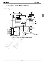
11. Asynchronous Serial interface (UART )
11.6 STOP Bit Length
TMP86PM29BUG
11.6 STOP Bit Length
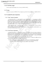
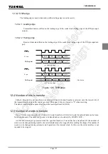
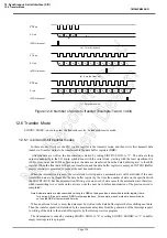
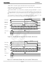
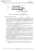
Select a transmit stop bit length (1 bit or 2 bits) by UARTCR1<STBT>.
11.7 Parity
Set parity / no parity by UARTCR1<PE> and set parity type (Odd- or Even-numbered) by UARTCR1<EVEN>.
11.8 Transmit/Receive Operation
11.8.1 Data Transmit Operation
Set UARTCR1<TXE> to “1”. Read UARTSR to check UARTSR<TBEP> = “1”, then write data in TDBUF
(Transmit data buffer). Writing data in TDBUF zero-clears UARTSR<TBEP>, transfers the data to the transmit
shift register and the data are sequentially output from the TXD pin. The data output include a one-bit start bit,
stop bits whose number is specified in UARTCR1<STBT> and a parity bit if parity addition is specified.
Select the data transfer baud rate using UARTCR1<BRG>. When data transmit starts, transmit buffer empty
flag UARTSR<TBEP> is set to “1” and an INTTXD interrupt is generated.
While UARTCR1<TXE> = “0” and from when “1” is written to UARTCR1<TXE> to when send data are
written to TDBUF, the TXD pin is fixed at high level.
When transmitting data, first read UARTSR, then write data in TDBUF. Otherwise, UARTSR<TBEP> is not
zero-cleared and transmit does not start.
11.8.2 Data Receive Operation
Set UARTCR1<RXE> to “1”. When data are received via the RXD pin, the receive data are transferred to
RDBUF (Receive data buffer). At this time, the data transmitted includes a start bit and stop bit(s) and a parity
bit if parity addition is specified. When stop bit(s) are received, data only are extracted and transferred to
RDBUF (Receive data buffer). Then the receive buffer full flag UARTSR<RBFL> is set and an INTRXD
interrupt is generated. Select the data transfer baud rate using UARTCR1<BRG>.
If an overrun error (OERR) occurs when data are received, the data are not transferred to RDBUF (Receive
data buffer) but discarded; data in the RDBUF are not affected.
Note:When a receive operation is disabled by setting UARTCR1<RXE> bit to “0”, the setting becomes valid when
data receive is completed. However, if a framing error occurs in data receive, the receive-disabling setting
may not become valid. If a framing error occurs, be sure to perform a re-receive operation.
Содержание TLCS-870/C Series
Страница 1: ...8 Bit Microcontroller TLCS 870 C Series TMP86PM29BUG ...
Страница 6: ...TMP86PM29BUG ...
Страница 7: ...Revision History Date Revision 2007 10 11 1 First Release 2008 8 29 2 Contents Revised ...
Страница 9: ......
Страница 15: ...vi ...
Страница 19: ...Page 4 1 3 Block Diagram TMP86PM29BUG 1 3 Block Diagram Figure 1 2 Block Diagram ...
Страница 23: ...Page 8 1 4 Pin Names and Functions TMP86PM29BUG ...
Страница 48: ...Page 33 TMP86PM29BUG ...
Страница 49: ...Page 34 2 Operational Description 2 3 Reset Circuit TMP86PM29BUG ...
Страница 61: ...Page 46 3 Interrupt Control Circuit 3 8 External Interrupts TMP86PM29BUG ...
Страница 81: ...Page 66 6 Watchdog Timer WDT 6 3 Address Trap TMP86PM29BUG ...
Страница 135: ...Page 120 10 8 Bit TimerCounter TC5 TC6 10 1 Configuration TMP86PM29BUG ...
Страница 145: ...Page 130 11 Asynchronous Serial interface UART 11 9 Status Flag TMP86PM29BUG ...
Страница 165: ...Page 150 13 10 bit AD Converter ADC 13 6 Precautions about AD Converter TMP86PM29BUG ...
Страница 183: ...Page 168 15 LCD Driver 15 4 Control Method of LCD Driver TMP86PM29BUG ...
Страница 201: ...Page 186 18 Electrical Characteristics 18 9 Handling Precaution TMP86PM29BUG ...
Страница 203: ...Page 188 19 Package Dimensions TMP86PM29BUG ...
Страница 205: ......

