Page 145
TMP86PM29BUG
13.3 Function
13.3.1 Software Start Mode
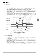
After setting ADCCR1<AMD> to “01” (software start mode), set ADCCR1<ADRS> to “1”. AD conver-
sion of the voltage at the analog input pin specified by ADCCR1<SAIN> is thereby started.
After completion of the AD conversion, the conversion result is stored in AD converted value registers
(ADCDR1, ADCDR2) and at the same time ADCDR2<EOCF> is set to 1, the AD conversion finished inter-
rupt (INTADC) is generated.
ADRS is automatically cleared after AD conversion has started. Do not set ADCCR1<ADRS> newly again
(Restart) during AD conversion. Before setting ADRS newly again, check ADCDR2<EOCF> to see that the
conversion is completed or wait until the interrupt signal (INTADC) is generated (e.g., interrupt handling rou-
tine).
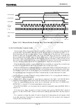
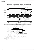
Figure 13-2 Software Start Mode
13.3.2 Repeat Mode
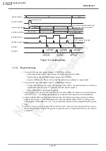
AD conversion of the voltage at the analog input pin specified by ADCCR1<SAIN> is performed repeatedly.
In this mode, AD conversion is started by setting ADCCR1<ADRS> to “1” after setting ADCCR1<AMD> to
“11” (Repeat mode).
After completion of the AD conversion, the conversion result is stored in AD converted value registers
(ADCDR1, ADCDR2) and at the same time ADCDR2<EOCF> is set to 1, the AD conversion finished inter-
rupt (INTADC) is generated.
In repeat mode, each time one AD conversion is completed, the next AD conversion is started. To stop AD
conversion, set ADCCR1<AMD> to “00” (Disable mode) by writing 0s. The AD convert operation is stopped
immediately. The converted value at this time is not stored in the AD converted value register.
ADCDR1 status
EOCF cleared by reading
conversion result
Conversion result
read
ADCDR2<EOCF>
INTADC interrupt request
ADCDR2<ADBF>
ADCCR1<ADRS>
1st conversion result
2nd conversion result
Indeterminate
AD conversion start
AD conversion start
ADCDR1
ADCDR2
Conversion result
read
Conversion result
read
Conversion result
read
Содержание TLCS-870/C Series
Страница 1: ...8 Bit Microcontroller TLCS 870 C Series TMP86PM29BUG ...
Страница 6: ...TMP86PM29BUG ...
Страница 7: ...Revision History Date Revision 2007 10 11 1 First Release 2008 8 29 2 Contents Revised ...
Страница 9: ......
Страница 15: ...vi ...
Страница 19: ...Page 4 1 3 Block Diagram TMP86PM29BUG 1 3 Block Diagram Figure 1 2 Block Diagram ...
Страница 23: ...Page 8 1 4 Pin Names and Functions TMP86PM29BUG ...
Страница 48: ...Page 33 TMP86PM29BUG ...
Страница 49: ...Page 34 2 Operational Description 2 3 Reset Circuit TMP86PM29BUG ...
Страница 61: ...Page 46 3 Interrupt Control Circuit 3 8 External Interrupts TMP86PM29BUG ...
Страница 81: ...Page 66 6 Watchdog Timer WDT 6 3 Address Trap TMP86PM29BUG ...
Страница 135: ...Page 120 10 8 Bit TimerCounter TC5 TC6 10 1 Configuration TMP86PM29BUG ...
Страница 145: ...Page 130 11 Asynchronous Serial interface UART 11 9 Status Flag TMP86PM29BUG ...
Страница 165: ...Page 150 13 10 bit AD Converter ADC 13 6 Precautions about AD Converter TMP86PM29BUG ...
Страница 183: ...Page 168 15 LCD Driver 15 4 Control Method of LCD Driver TMP86PM29BUG ...
Страница 201: ...Page 186 18 Electrical Characteristics 18 9 Handling Precaution TMP86PM29BUG ...
Страница 203: ...Page 188 19 Package Dimensions TMP86PM29BUG ...
Страница 205: ......

