9
© February 2007 TOSHIBA TEC CORPORATION All rights reserved
e-STUDIO167/207/237
DRIVE UNIT
9 - 9
(7)
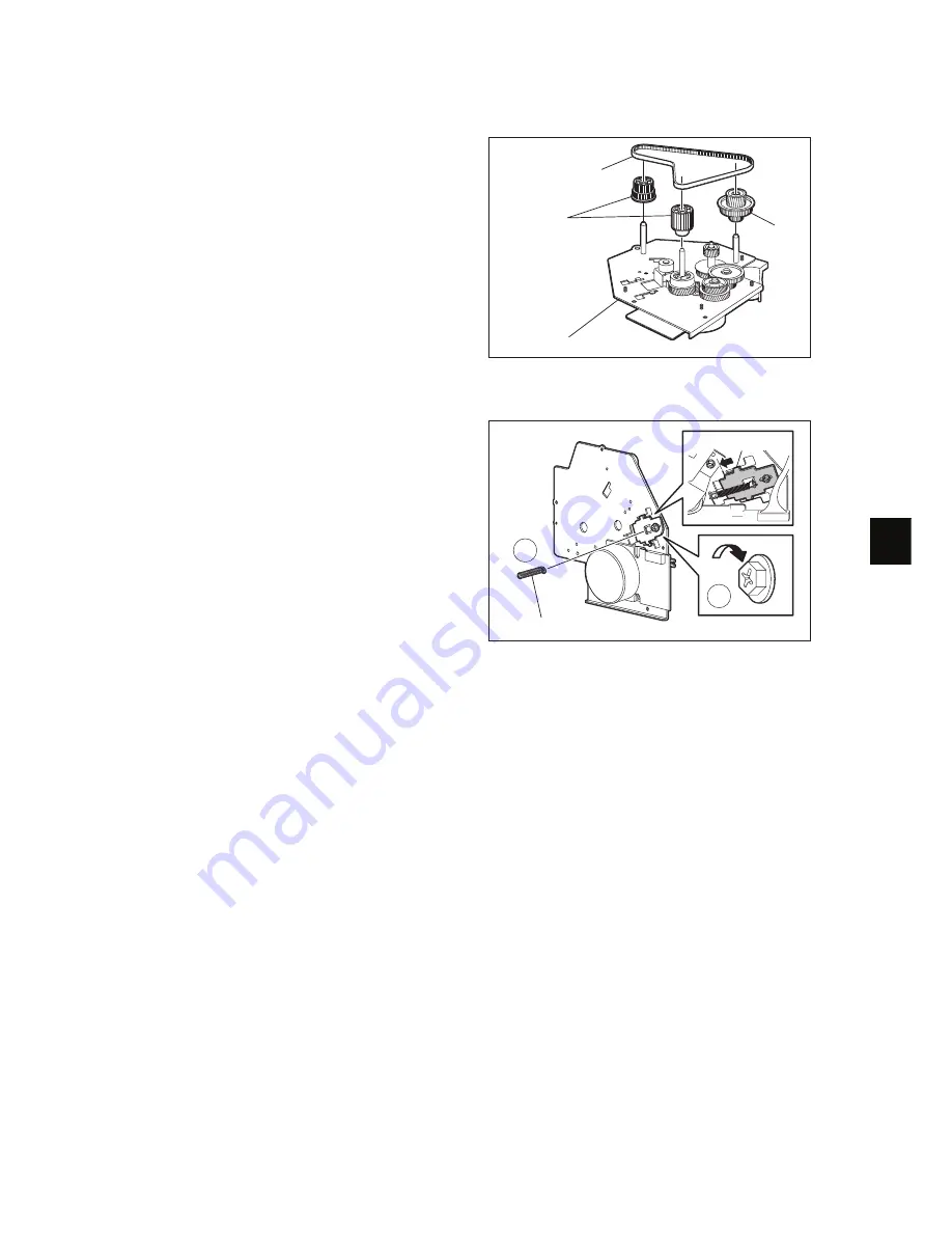
Take off the gear and timing belt from the
main motor drive unit.
Notes:
•
Do not apply more tension to the belt of
the main motor drive unit than that pro-
duced by the spring force.
•
Follow the procedure bellow to perform
tension adjustment when assembling the
main motor drive unit.
-
Align the tensioner with the punch
mark and tighten the tensioner fixing
screw.
-
Hook the tensioner spring.
-
Install the main motor drive unit to the
equipment.
-
Loosen the tensioner fixing screw.
-
Let the spring force produce tension
for the belt, and tighten the fixing
screw.
Fig. 9-10
Fig. 9-11
Gear
Gear
Timing belt
Main motor drive unit
1
2
Tensioner spring
Tensioner
Содержание E-Studio167
Страница 8: ...e STUDIO167 207 237 February 2007 TOSHIBA TEC CORPORATION All rights reserved CONTENTS 4 ...
Страница 54: ...e STUDIO167 207 237 February 2007 TOSHIBA TEC CORPORATION All rights reserved OUTLINE OF THE MACHINE 2 38 ...
Страница 68: ...e STUDIO167 207 237 February 2007 TOSHIBA TEC CORPORATION All rights reserved COPY PROCESS 3 14 ...
Страница 92: ...e STUDIO167 207 237 February 2007 TOSHIBA TEC CORPORATION All rights reserved CONTROL PANEL 5 10 ...
Страница 132: ...e STUDIO167 207 237 February 2007 TOSHIBA TEC CORPORATION All rights reserved LASER OPTICAL UNIT 8 8 ...
Страница 142: ...e STUDIO167 207 237 February 2007 TOSHIBA TEC CORPORATION All rights reserved DRIVE UNIT 9 10 ...
Страница 192: ...e STUDIO167 207 237 February 2007 TOSHIBA TEC CORPORATION All rights reserved DRUM RELATED SECTION 11 22 ...
Страница 214: ...e STUDIO167 207 237 February 2007 TOSHIBA TEC CORPORATION All rights reserved DEVELOPMENT SYSTEM 12 22 ...
Страница 260: ...e STUDIO167 207 237 February 2007 TOSHIBA TEC CORPORATION All rights reserved POWER SUPPLY UNIT 15 8 ...
Страница 264: ...e STUDIO167 207 237 February 2007 TOSHIBA TEC CORPORATION All rights reserved PC BOARDS 16 4 8 PWA F ADU Fig 16 8 ...
Страница 265: ......
Страница 266: ......


