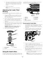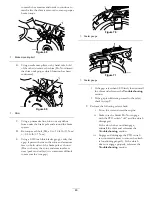
the sail area only (Figure 97). Repeat this procedure
until the blade is balanced.
Figure 97
1.
Blade
2.
Balancer
Installing the Blades
1.
Install the blade onto the spindle shaft (Figure 98).
Important:
The curved part of the blade must be
pointing upward toward the inside of the mower to
ensure proper cutting.
2.
Install the spring disk and blade bolt. The spring disk
cone must be installed toward the bolt head (Figure 98).
Torque the blade bolt to 85-110 ft-lb (115-150 N-m).
59
Содержание 74901 Z Master 5000
Страница 28: ...Figure 40 1 Trailer 3 Not greater than 15 degrees 2 Full width ramp 4 Full width ramp side view 28 ...
Страница 66: ...Schematics Wire Diagram Rev A 66 ...
Страница 67: ...Notes 67 ...

