1
3
2
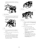
G017027
Figure 88
1.
Deck lift pedal
3.
Transport lock
2.
Height of cut pin
6.
Insert the height adjustment pin into the 3 inch (7.6
cm) cutting height location.
7.
Release the transport lock and allow the deck to lower
to the cutting height.
8.
Raise the discharge chute.
9.
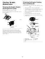
On both sides of the deck, measure from the level
surface to the front tip of the blade (Postion A).
The measurement should read 3 inches (7.6 mm)
(Figure 89).
Figure 89
1.
3 inches (7.6 cm) at A is
correct
3.
Measure here from the
blade tip to hard surface
2.
3 1/4 inches (8.3 cm) at B
is correct
4.
Measure at A and B on
both sides
10.
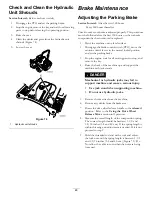
If needed, loosen the whizlock nut on the side of the
yoke and the jam nut on top. Fine tune the screw
adjuster by turning it to get 3 inch (7.6 mm) height (see
Figure 90).
To increase the height, turn the adjuster screw
clockwise; to decrease, turn counterclockwise.
Figure 90
1.
Whizlock nut
3.
Jam nut
2.
Adjuster screw
4.
Yoke
11.
If the front deck links do not have enough adjustment
to achieve accurate cut height , the single point
adjustment can be utilized to gain more adjustment.
12.
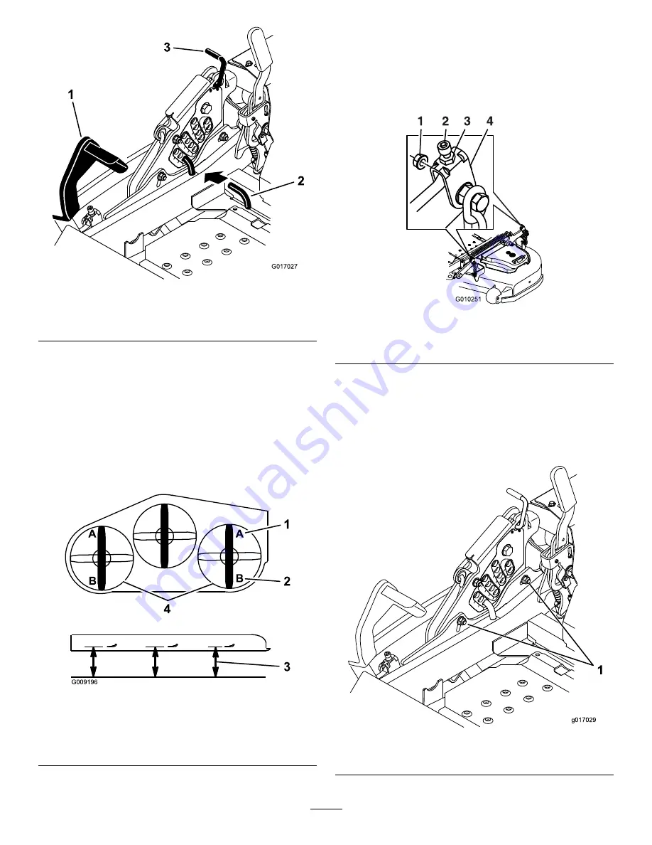
To adjust the single point system, loosen the two bolts
at the bottom of the height of cut plate. Refer to
Figure 91.
1
g017029
Figure 91
1.
Bolts at the bottom of the height-of-cut plate
56
Содержание 74901 Z Master 5000
Страница 28: ...Figure 40 1 Trailer 3 Not greater than 15 degrees 2 Full width ramp 4 Full width ramp side view 28 ...
Страница 66: ...Schematics Wire Diagram Rev A 66 ...
Страница 67: ...Notes 67 ...

