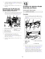
Figure 83
1.
Retainer
3.
Plug
2.
Quick-connect socket
2.
Remove the plug from the socketed quick-connect
fitting (
Note:
You no longer need the plug.
3.
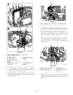
Remove the 3 retainers that secure the bypass manifold
to the spray valve manifold (
).
Figure 84
1.
Quick-connect fitting
(bypass valve)
3.
Quick-connect fitting
(spray valve manifold)
2.
Bypass valves
4.
Retainer
4.
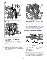
Lift the bypass manifold from the spray valve manifold
(
).
5.
Rotate the bypass manifold 180° and seat it onto the
3 quick-connect fittings of the spray valve manifold
(
).
Figure 85
1.
Bypass
manifold—quick-connect
socket
3.
Quick-connect fitting
(spray valve manifold)
2.
Quick-connect fitting
(bypass valve)
4.
Retainer
6.
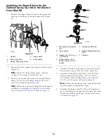
Secure the bypass manifold to the quick-connect
fittings of the spray valve manifold (
) with the
3 retainers that you removed in step
7.
Assemble the cap onto the quick-connect fitting (
) with the retainer that you removed in step
.
Figure 86
1.
Cap
3.
Retainer
2.
Quick-connect fitting
41
Содержание 136-0372
Страница 61: ...Schematics Flow Diagram Rev A 61...
Страница 62: ...Notes...
Страница 63: ...Notes...
Страница 64: ......


