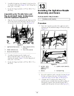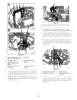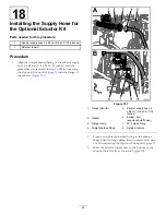
Figure 80
1.
Retainer
5.
Straight barbed
fitting—supply hose for the
left-boom section—2 x 205
cm (3/4 x 80-13/16 inches)
2.
Quick-connect fitting
(left-boom-section valve)
6.
Straight barbed
fitting—supply hose for the
center-boom section—2
x 58 cm (3/4 x 22-13/16
inches)
3.
Quick-connect fitting
(center-boom-section
valve)
7.
Straight barbed
fitting—supply hose for
the right-boom section—2
x 170 cm (3/4 x 66-13/16
inches)
4.
Quick-connect fitting
(right-boom-section valve)
3.
Secure the straight barbed fitting to the quick-connect
fitting with the retainer that is supplied with the hose
(
).
Installing the Supply Hoses to the
Boom Sections
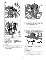
1.
Assemble the center boom-supply hose onto the
T-fitting at the center-boom section (
Figure 81
1.
Center boom-section valve
4.
Supply hose (center-boom
section)
2.
Center-boom section
5.
Hose clamp
3.
Left side of the machine
6.
Barbed T-fitting
2.
Secure the hose to the T-fitting with a hose clamp that
you removed in step
of
.
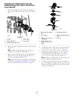
3.
Route the right boom-supply hose through the support
clamp at the end of the center-boom section (
39
Содержание 136-0372
Страница 61: ...Schematics Flow Diagram Rev A 61...
Страница 62: ...Notes...
Страница 63: ...Notes...
Страница 64: ......


