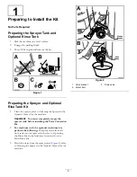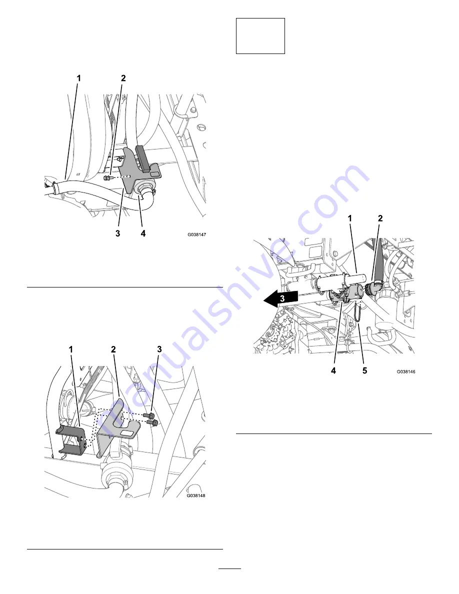
Removing the Bracket for the Agitation
Throttle Mount
1.
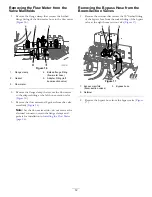
Remove the 2 flange-head bolts (5/16 x 5/8 inch) that
secure the agitation throttle valve to the throttle-valve
bracket (
).
Figure 21
1.
Agitation supply hose
3.
Bracket (throttle valve)
2.
Flange-head bolt (5/16 x
5/8 inch)
4.
Agitation throttle valve
2.
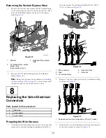
Remove the 2 flange-head bolts (5/16 x 3/4 inch) that
secure the throttle-valve bracket to the throttle-valve
mount, and remove the bracket (
).
Note:
You no longer need the 4 flange-head bolts and
throttle-valve bracket.
Figure 22
1.
Mount (throttle-valve
bracket)
3.
Flange-head bolt (5/16 x
3/4 inch)
2.
Bracket (throttle valve)
7
Removing the Agitation, Rate,
and Master-Spray Valves
No Parts Required
Disconnecting the Return,
Sprayer-Supply, and Bypass Hoses
1.
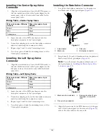
At the back of the machine, remove the retainer that
secures the 90° barbed fitting of the return hose to the
T-fitting located inboard of the pressure-relief valve
(
).
Note:
Retain the retainers for installation in
the Return Hose (page 31)
.
Figure 23
1.
Pressure-relief valve
4.
T-fitting
2.
90° barbed fitting (return
hose)
5.
Retainer
3.
Front of the machine
2.
Remove the 90° barbed fitting from the T-fitting
(
).
3.
Remove the retainer that secures the 90° barbed fitting
of the sprayer supply hose to the T-fitting located
forward of the pressure-relief valve (
).
Note:
Retain the retainers for installation in
the Sprayer Supply Hose—Machine without the
Optional Eductor Kit (page 34)
.
14
Содержание 136-0372
Страница 61: ...Schematics Flow Diagram Rev A 61...
Страница 62: ...Notes...
Страница 63: ...Notes...
Страница 64: ......


