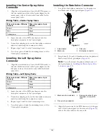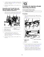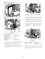
Figure 63
1.
Agitation-nozzle assembly
3.
90° quick-connect fitting
2.
Retainer
4.
Quick-connect fitting
(agitation throttle valve)
14
Installing the Return Hose,
Agitation Supply Hose, and
Bypass Hose
Parts needed for this procedure:
1
Return hose—2.5 x 72 cm (1 x 27-7/8 inches)
1
Agitation supply hose—2.5 x 72 cm (1 x 28-1/4 inches)
1
Bypass hose—2.5 x 110 cm (1 x 43-1/2
inches)—machines without the optional spray wand
or electric hose reel kit
Installing the Return Hose
1.
Assemble the quick-connect fitting (straight barbed) of
the return hose—2.5 x 71 cm (1 x 27-7/8 inches) onto
the quick coupling of the rate valve with the retainer
(small) that is supplied with the hose (
).
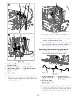
Figure 64
1.
Quick-connect fitting (rate
control valve)
5.
Return hose—2.5 x 71 cm
(1 x 27-7/8 inches)
2.
Quick-connect fitting
(straight barbed—return
hose)
6.
90° barbed fitting
3.
Retainer (small)
7.
Retainer (large)
4.
Front of the machine
8.
T-fitting (inboard)
2.
Route the return hose down and toward the T-fitting
located inboard of the pressure-relief valve as shown
in
.
31
Содержание 136-0372
Страница 61: ...Schematics Flow Diagram Rev A 61...
Страница 62: ...Notes...
Страница 63: ...Notes...
Страница 64: ......


