


15
Control panel
HELIX
4.1
SurefIre™ heATer BlocK coNTrol
i
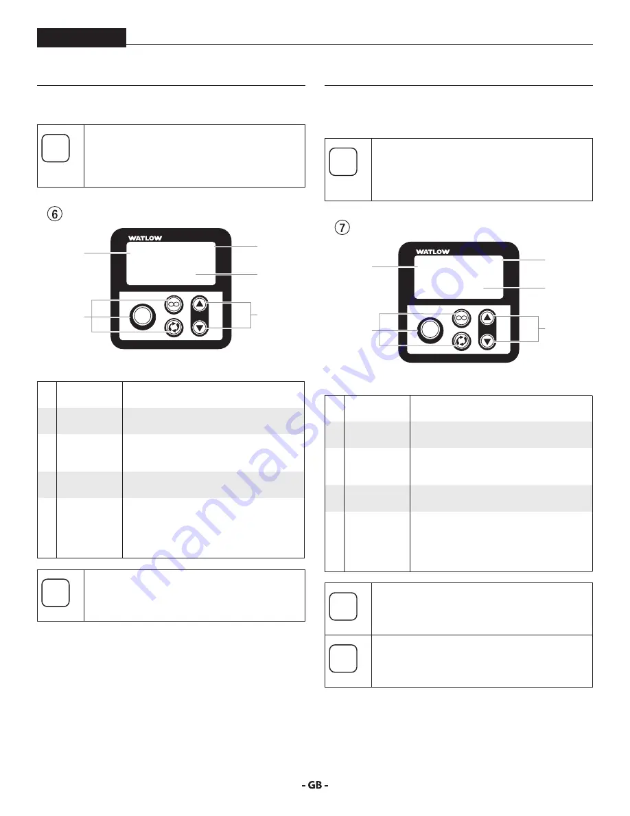
Refer to item 8 in section 4. The block heater
control regulates the temperature of spray
material as it passes through the heater block,
prior to it reaching the heated hoses.
1
EZ-ZONE
ºF
ºC
Z
O
N
E
8.8:8.8
8 8.8:8.8
EZ
2
1
3
4
5
1
Temperature
display
Shows actual temperature of the heater
block.
2
Programming
buttons
These are non-functioning factory
programming buttons. Do not use.
3
Power
indicator
The flashing or steady “1” indicates sufficient
power is being delivered to the system’s
electrical relay.
4
Temperature
setting
Shows the desired temperature of the heater
block set by the operator
5
Temperature
adjustment
These buttons will increase (
p
) or decrease
(
q
) the temperature of the heater block.
The temperature will change in increments
of 1ºF. Press and hold the button to increase
the increments by 1ºF and then 10ºF.
i
Refer to section 8.2 to review the controller error
messages.
4.2
SurefIre™ heATeD hoSe TemperATure
coNTrol
i
Refer to item 1 in section 4. The heated hose
temperature control maintains the temperature
of the spray material once it passes through the
heater block and into the heated hoses.
1
EZ-ZONE
ºF
ºC
Z
O
N
E
8.8:8.8
8 8.8:8.8
EZ
2
1
3
4
5
1
Display
Displays the current temperature of the
heated hose set
2
Programming
buttons
These are non-functioning factory
programming buttons. Do not use.
3
Power
indicator
The flashing or steady “1” indicates sufficient
power is being delivered to the system’s
electrical relay.
4
Temperature
setting
Shows the desired temperature of the
heated hoses set by the operator
5
Temperature
adjustment
These buttons will increase (
p
) or decrease
(
q
) the temperature of the heated hose set.
The temperature will change in increments
of 1ºF. Press and hold the button to increase
the increments by 1ºF and then 10ºF.
i
Refer to section 8.2 to review the controller error
messages.
i
Decreased voltage under 230V AC may increase
initial heat time.
Содержание HELIX 0138011
Страница 12: ...12 SYSTEM DESCRIPTION HELIX A E D F L1 J H K K J N M M B H L2 G I C 3 3 System Diagram with circulation ...
Страница 44: ...44 HELIX Spare parts diagram drive assembly 4 5 6 1 2 3 7 8 9 10 11 18 17 12 13 14 15 16 ...
Страница 50: ...50 HELIX Spare parts diagram fluid section 1 2 3 4 7 8 15 16 17 18 19 20 21 22 23 9 10 11 12 13 14 5 6 ...


